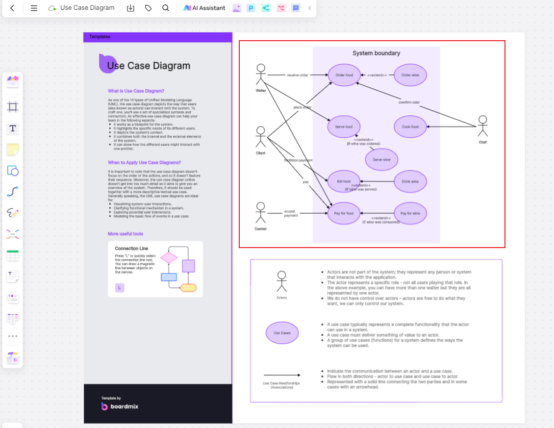
A Use Case Diagram is a graphical modeling tool in UML (Unified Modeling Language) used to depict the interactions between a system and its external entities. As a crucial tool for requirement analysis and system design, a Use Case Diagram helps team members understand the system’s functional requirements and interaction processes, facilitating effective system design and development. This article will provide an in-depth analysis of Use Case Diagrams, covering their definition, purposes, application cases, and usage techniques to help readers fully leverage this powerful tool, optimize the development process, and ensure the system meets user expectations.
Three Components of a Use Case Diagram
Actors: Actors represent external entities interacting with the system, such as people, other systems, or devices. In a Use Case Diagram, actors are depicted by simple icons, usually a stick figure or a rectangular box.

Use Cases: Use cases describe the interaction processes between the system and external actors, providing an abstract description of system behavior. Each use case in the diagram has a name and a unique identifier and can be associated with other use cases to form relationships.

Relationships: These depict the interactions between actors and use cases or between different use cases. Common types include associations, inclusions, extensions, and generalizations, usually represented by different lines and arrows.
Four Common Relationship Types in Use Case Diagrams
The table below summarizes the common relationship types between actors and use cases, and between use cases themselves, along with their representations in the diagram:
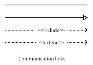
Association
The association represents the interaction between an actor and a use case or between two use cases, indicating communication or interaction. For example, in an e-commerce system, there is an association between "Browse Products" and "Add to Cart," as well as between "User" and "Purchase Products."
Include
In this relationship, a use case includes another use case to achieve more complex functionality. For instance, in a banking system, "Transfer Funds" might include "Verify Balance," and "Withdraw Cash" might include "Authenticate User."
Extend
This relationship allows a use case to extend another use case to add additional functionalities. For example, in a hotel booking system, "Book Room" might extend to "Select Additional Services," and "Login" might extend to "Forgot Password."
Generalization
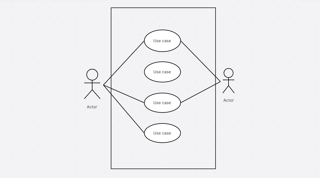
Used to represent that a use case is a specialized form or sub-use case of another base use case. For example, "Buy Used Car" is a specialized form of "Buy Car," and "Login with Account" are sub-use case of "Login to System."
The Role of Use Case Diagrams
Requirement Analysis: Use Case Diagrams present the system’s functional requirements, aiding team members in understanding the system's behavior and functionality. They help define the system’s functional boundaries and the interactions with external actors.
System Design: They transform functional requirements into executable tasks and operations, helping the team identify and define the main functional modules and their interrelations and dependencies.
Communication and Collaboration: Use Case Diagrams allows team members to quickly grasp the functional requirements and interaction relationships, fostering better understanding and collaboration. They also facilitate effective communication with clients and stakeholders.
Validation and Testing: These diagrams clarify the system’s functional requirements and the expected behaviors of actors, assisting the testing team in designing and executing effective test cases. They help verify whether the system meets the requirements and identify and resolve potential issues and risks.
How to Draw a Use Case Diagram
Choose a Suitable Drawing Tool
Here, we recommend a powerful online drawing tool—Boardmix. It offers robust drawing functionalities and supports efficient team collaboration.
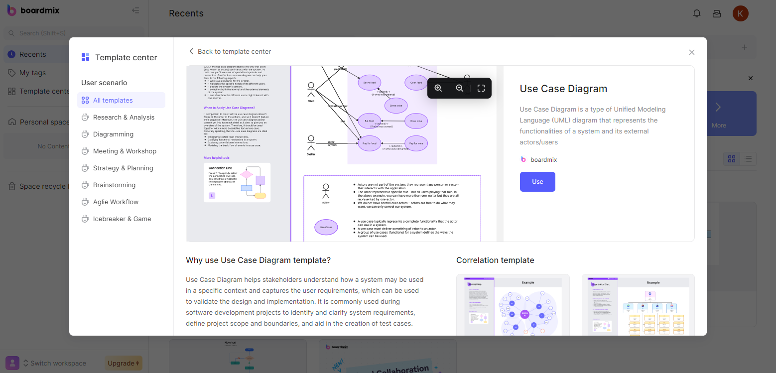
Standard symbols and customization options
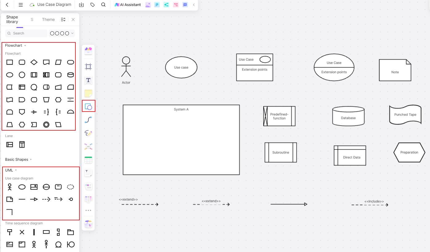
Boardmix provides a library of standard use case diagram symbols and supports text, fill color, line direction, and color customization. It also offers quick access to official configuration styles, making it easy to use!
Efficient team collaboration
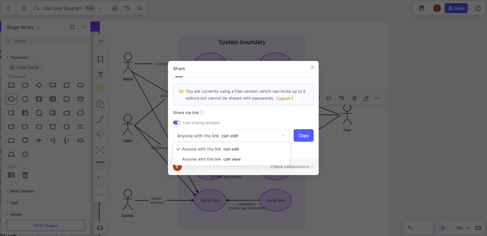
Boardmix supports real-time collaboration, allowing project teams to discuss around a shared whiteboard, edit documents online, conduct remote presentations, and hold audio/video meetings anytime, anywhere.
Rich template resources
The Boardmix community section offers a wealth of templates, including Use Case Diagrams, available for free use to help you quickly create your diagrams!
Drawing Steps
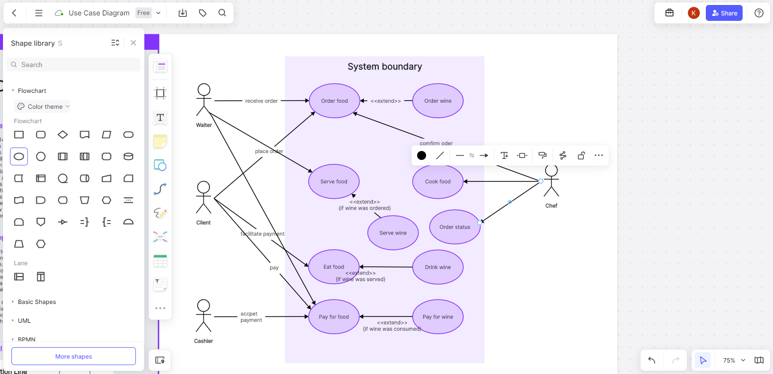
Identify Actors: Determine the external actors interacting with the system, such as users, other systems, or entities.
Identify Use Cases: Identify the system’s functional requirements, representing user goals or system operations. Each use case represents a specific function or business scenario.
Establish Relationships Between Actors and Use Cases: Use lines to connect actors with the use cases they are involved in, indicating the interactions.
Add Relationship Types: Add associations, includes, extends, and generalizations to appropriately describe the interactions between use cases.
Detail Use Cases: For complex use cases, break them down into smaller sub-use cases to better describe the system’s functionality.
Application Analysis of Use Case Diagrams
Online Shopping System Use Case Diagram
Suppose we are developing an online shopping system with roles like regular users and system users, supporting functionalities such as browsing products, adding products to the cart, searching for products, and submitting orders. By identifying all actors and their relationships with use cases, we can draw the Use Case Diagram.
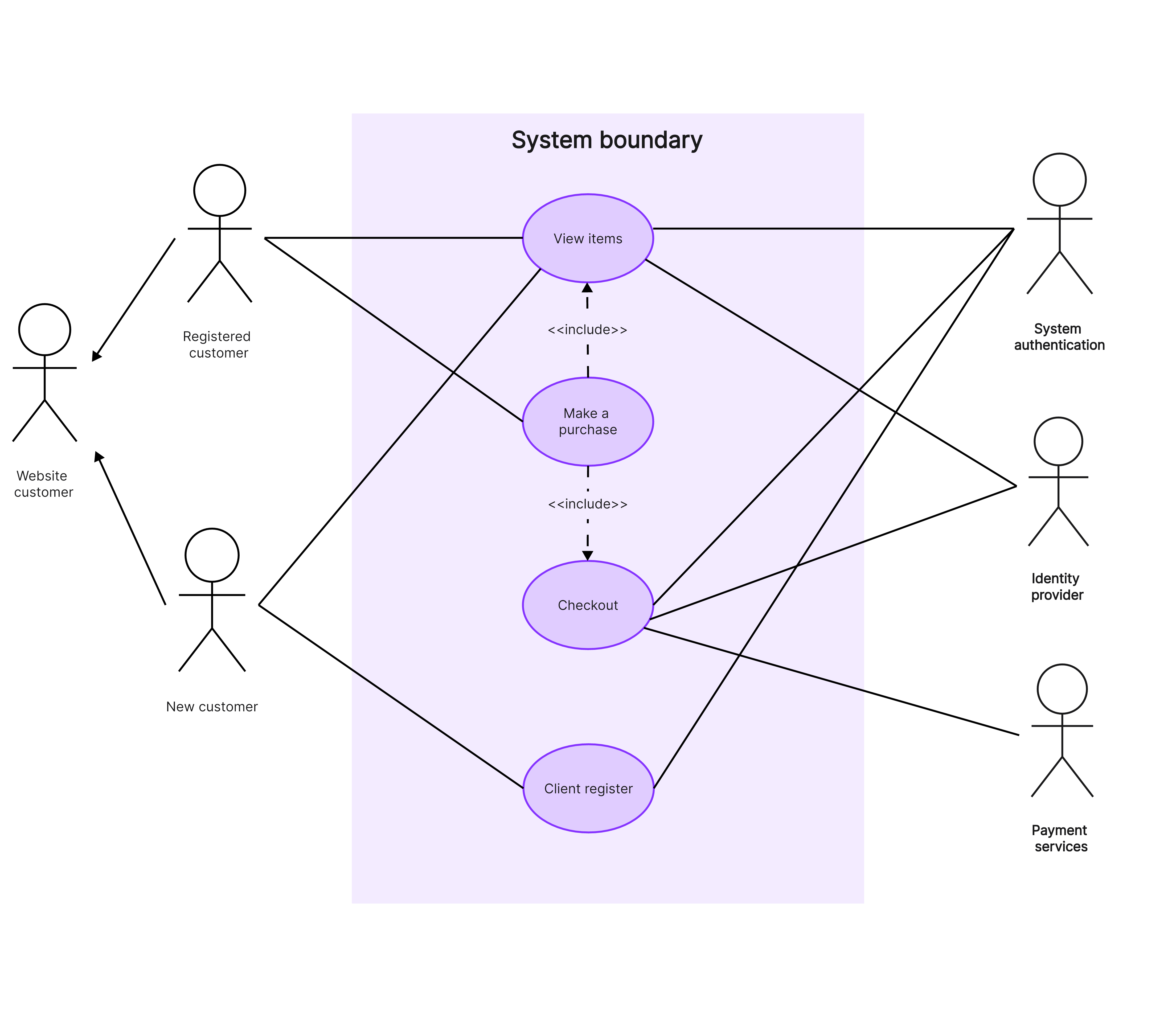
The diagram presents the main functions and interactions, helping the development team understand the user's needs and expectations during the shopping process. It defines core functions like product browsing and cart management, ensuring the system meets basic shopping requirements. UI designers can also better understand the interaction flow, designing user-friendly interfaces and processes, and enhancing user experience.
Hospital Appointment System Use Case Diagram
Suppose we are developing a hospital appointment system with roles like patients, nurses, registration desk, and administrators, supporting functionalities like viewing doctor schedules, making appointments, and canceling appointments.
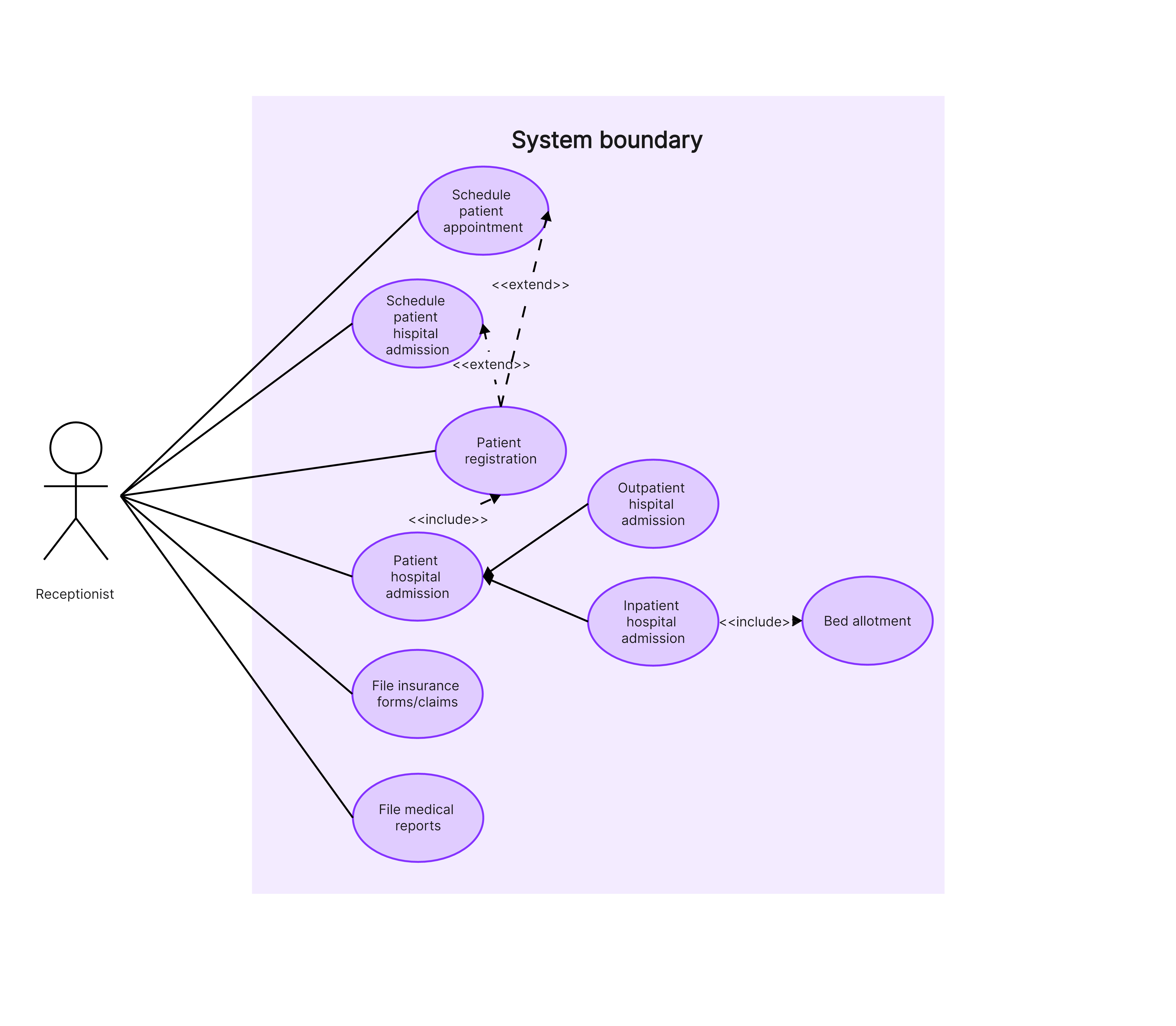
The diagram helps the development team understand user needs better, designing a system that meets user expectations, thus improving user satisfaction and hospital operational efficiency. It also aids the team in considering potential issues and exceptions during development, increasing efficiency and system quality.
In conclusion, Use Case Diagrams are essential tools for requirement analysis and system design, facilitating communication and understanding, and optimizing system design. For a powerful combination of functionality, ease of use, collaboration, and creativity, we highly recommend Boardmix. It enhances thinking capabilities and promotes teamwork and creativity.


