Decoding a Network Topology Diagram can feel like navigating a complex maze. It's about understanding how different network nodes are interconnected, ensuring smooth data transmission and optimal network performance. But this isn't just about identifying nodes and connections. It's about comprehending the underlying structure that governs network connectivity and functionality. So, how do you decode these diagrams? What key elements should you focus on to understand the connectivity map of your network? And most importantly, how can this decoding process enhance your ability to manage and optimize your network infrastructure? Let's explore these questions together, delving into the art of decoding Network Topology Diagrams for effective network management.
What is Network Topology
Network topology refers to the physical layout or structure of a computer network. It shows how devices, such as computers, routers, switches, and servers, are connected and arranged within a network. Network topology can be visualized as a map or diagram that depicts the relationships and connections between network components.
Types of Network Topologies
The choice of network topology depends on factors such as scalability, performance requirements, cost, and the specific needs of the organization or network. Different topologies offer different advantages and disadvantages in terms of ease of management, fault tolerance, and scalability. There are several types of network topologies, including:
Bus Network Topology
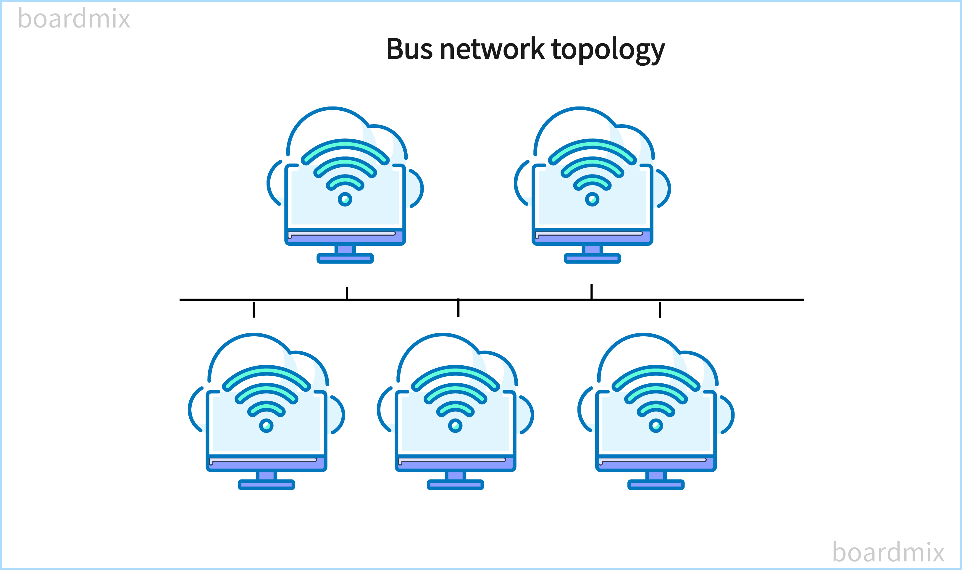
In this topology, all devices are connected to a common communication line called a bus. Each device receives every message transmitted on the bus but only processes messages addressed to it.
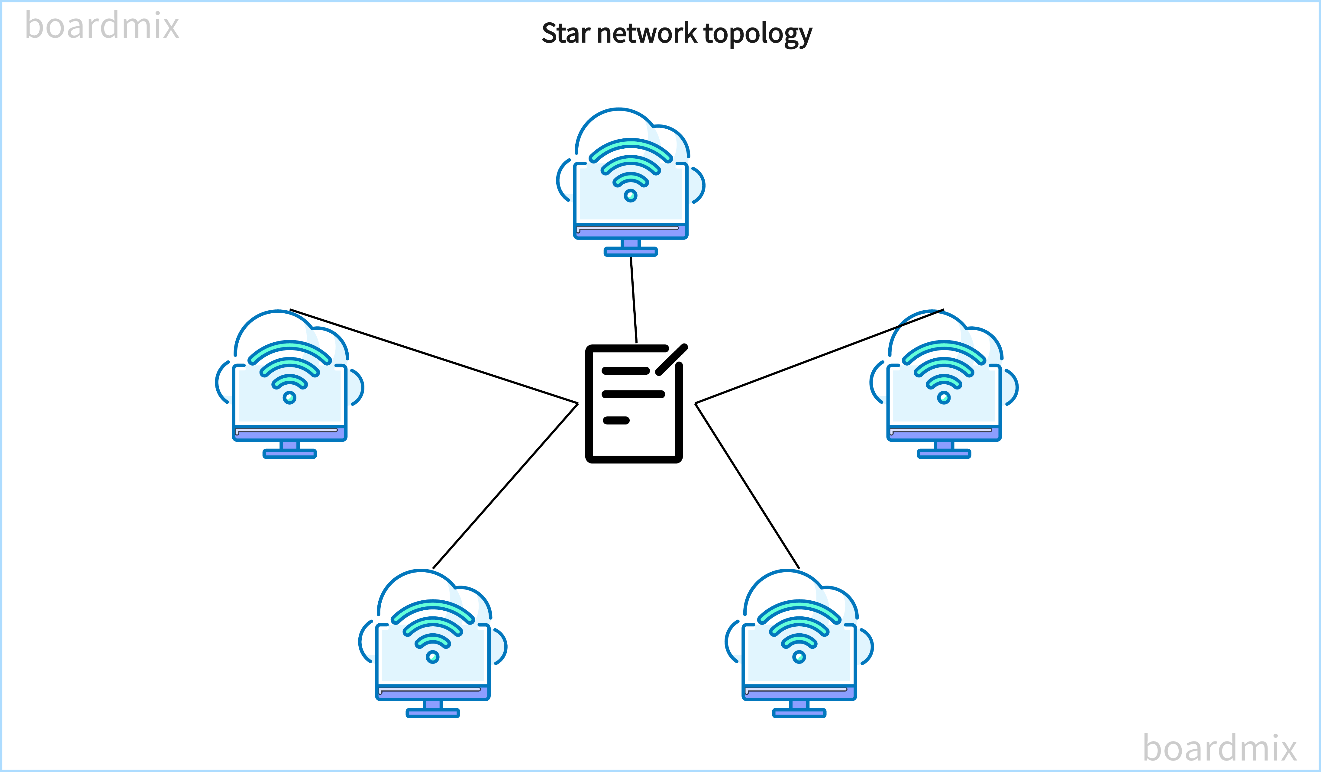
Star Network Topology
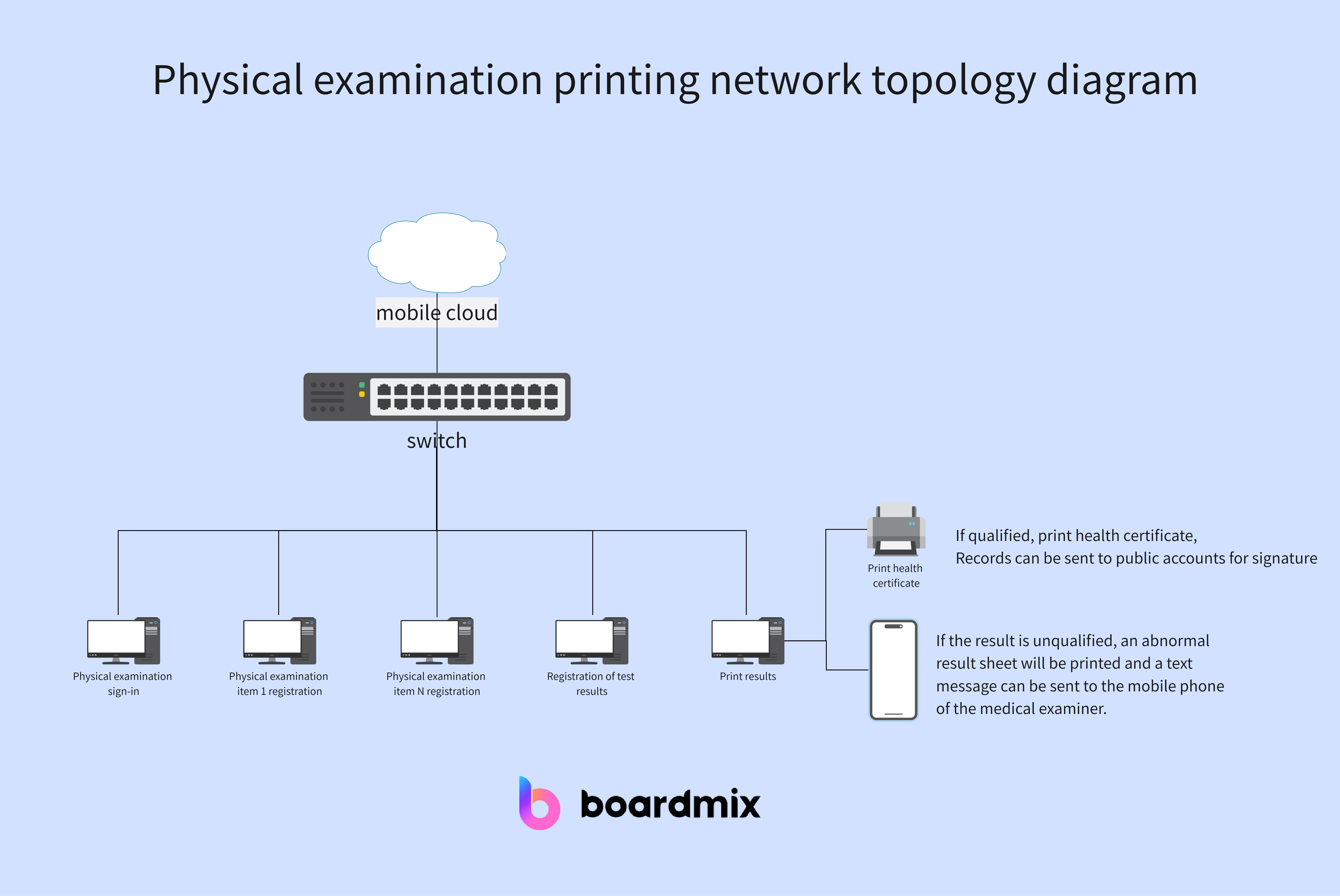
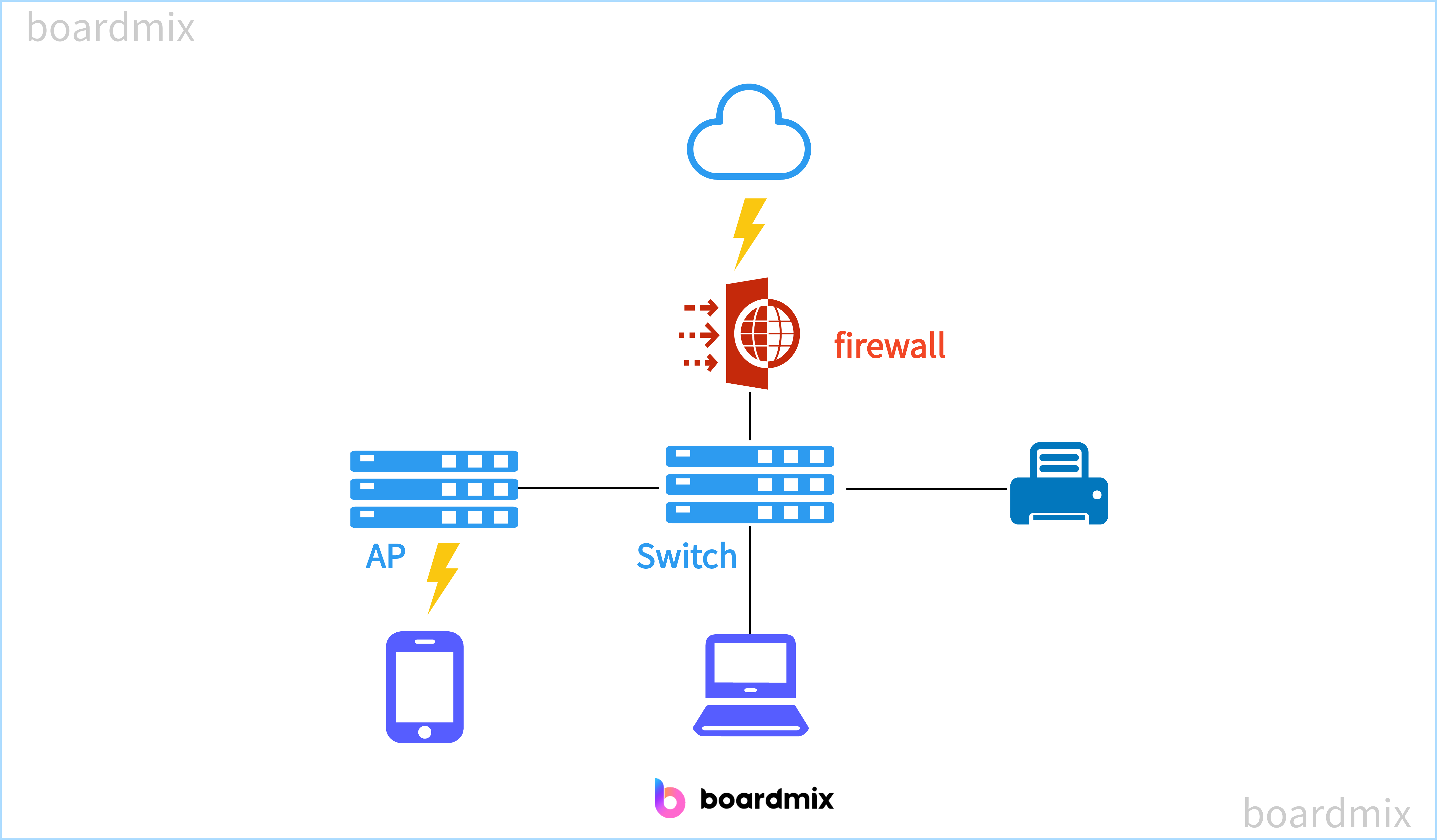
In this topology, all devices are connected to a central device, such as a switch or hub. All data is transmitted through the central device, which controls the flow of information between devices.
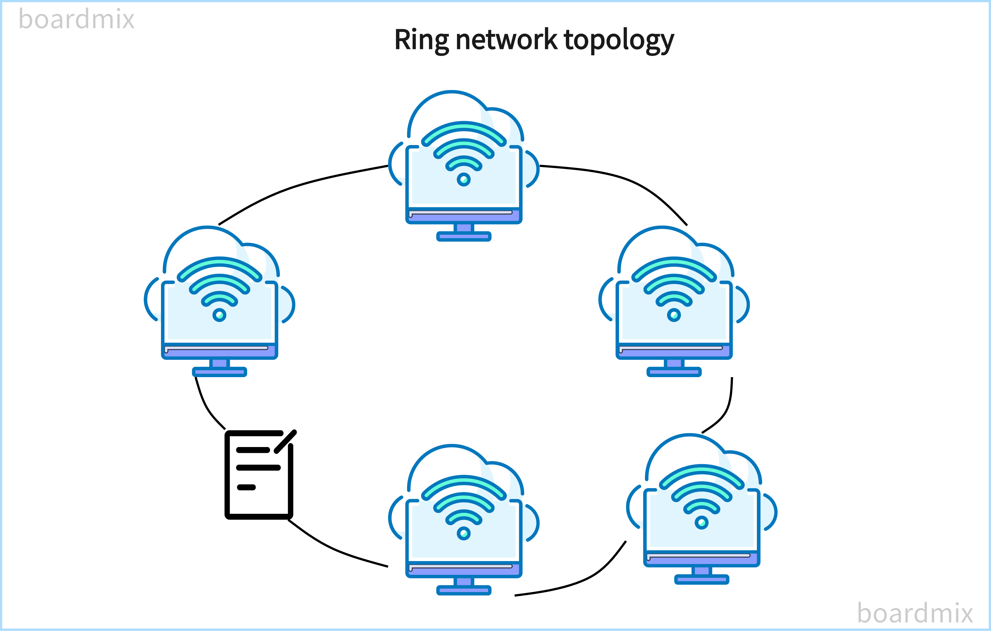
Ring Network Topology
In this topology, devices are connected circularly, forming a closed loop. Each device receives and forwards messages in a sequential order until the intended recipient receives the message.
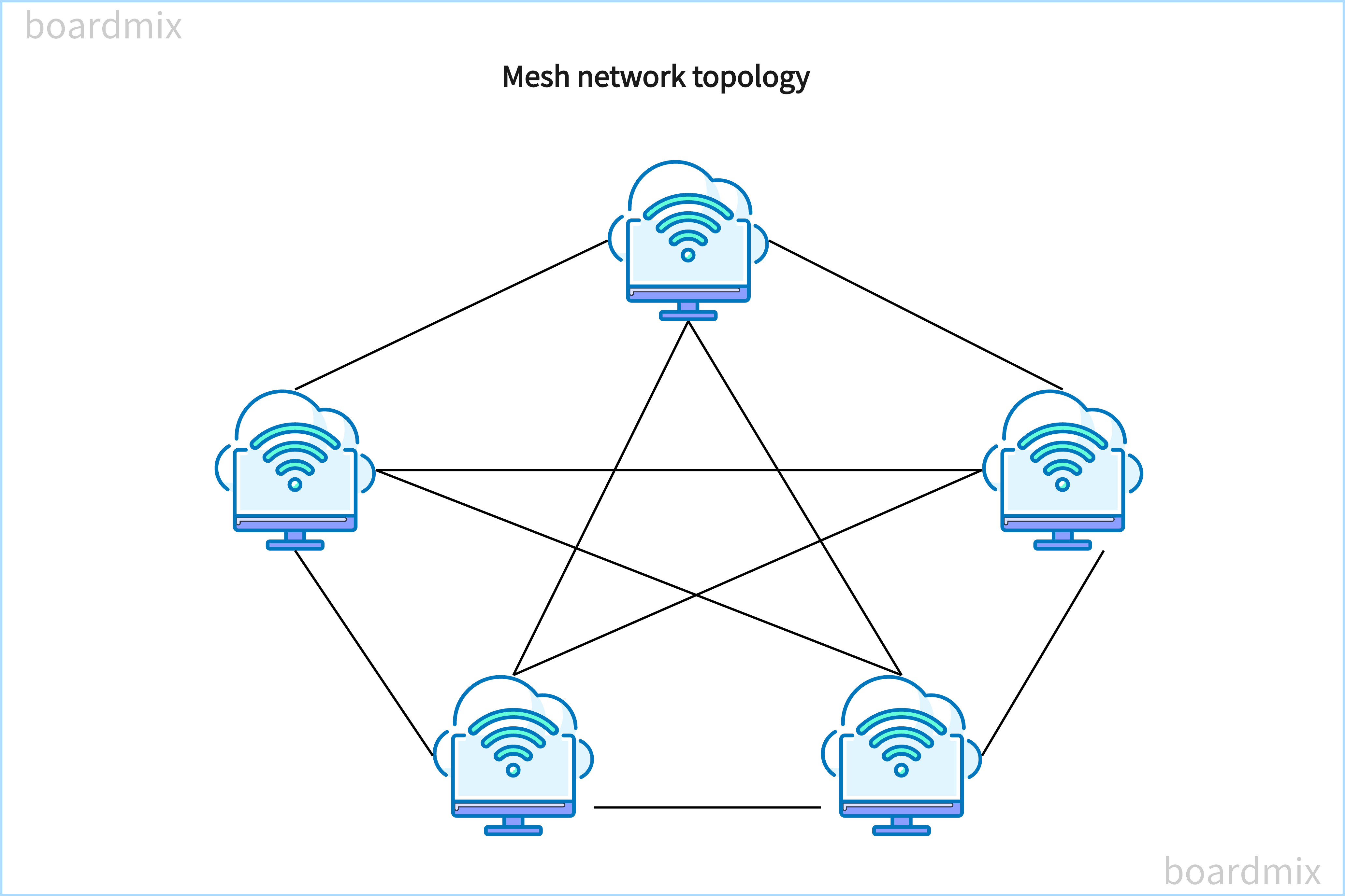
Mesh Network Topology
In this topology, each device is connected to every other device in the network. This creates multiple paths for data transmission, improving network reliability and fault tolerance.
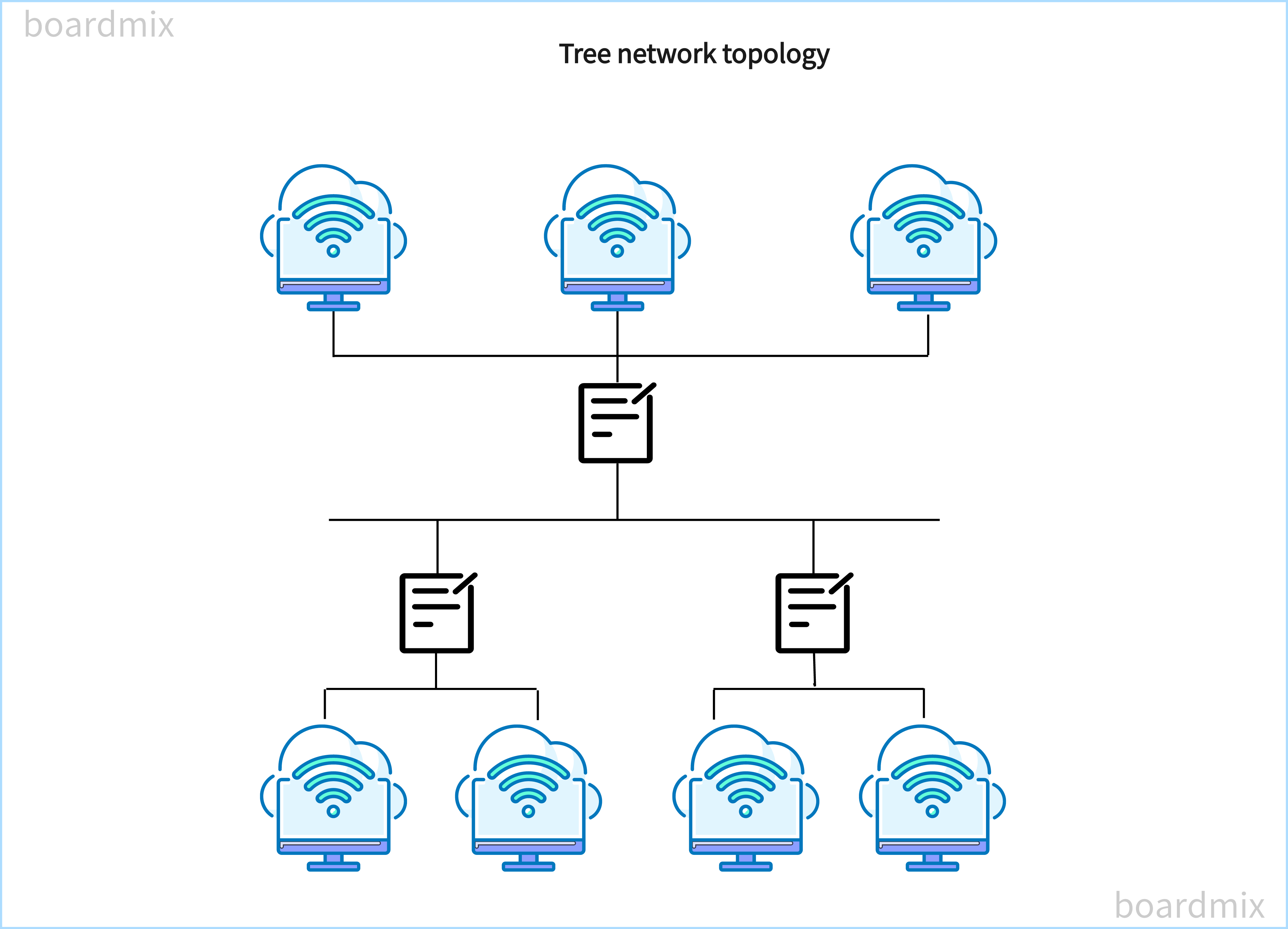
Tree Network Topology
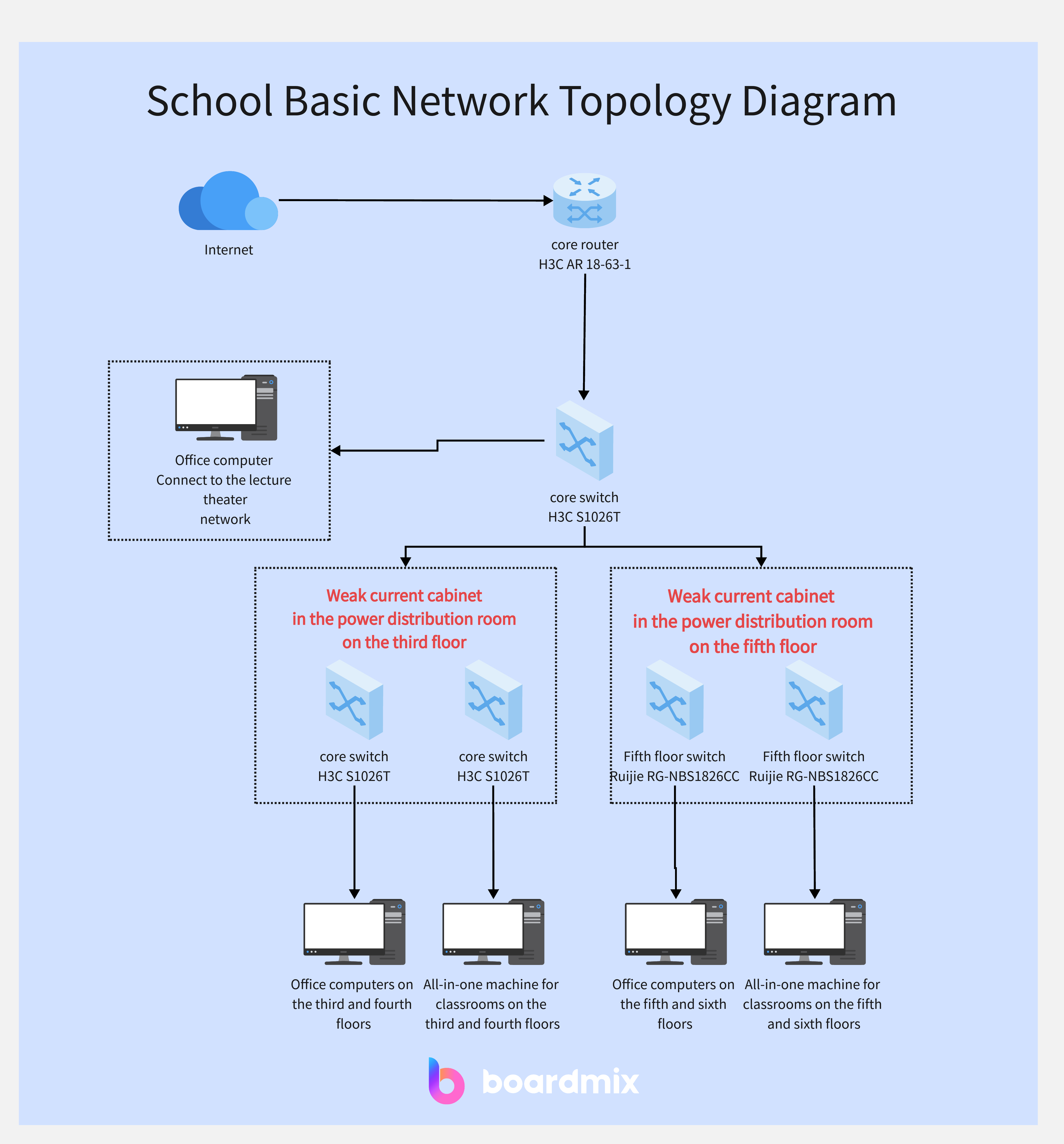
Also known as a hierarchical topology, this structure resembles a tree, with multiple levels of devices branching out from a root device. Each level may have its own switch or hub to connect devices.
Network administrators and IT professionals need to understand network topology in order to design, implement, and troubleshoot computer networks effectively.
Why Network Topology is Important in System Design?
Network topology plays a crucial role in system design as it directly impacts the performance, scalability, and reliability of a computer network. Here are some key roles that network topology plays in system design.
- Scalability: Network topology determines how easily a network can be scaled to accommodate additional devices or increased network traffic. Different topologies have varying levels of scalability, with some offering more flexibility than others. For example, a mesh topology allows for easy expansion by adding more connections, while a bus topology may become congested and less scalable as more devices are added.
- Performance: The network topology affects the speed and efficiency of data transmission within a network. The choice of topology can impact factors such as latency, bandwidth, and throughput. For instance, a star topology with a central device can provide faster data transmission as it does not require messages to pass through multiple devices. On the other hand, a ring topology may introduce more latency due to the sequential forwarding of messages.
- Fault Tolerance: Network topology determines how resilient a network is to failures or disruptions. Redundancy is an important consideration in system design to ensure uninterrupted connectivity and data flow. Topologies like mesh or ring offer built-in redundancy as they provide multiple paths for data transmission. If one path fails, data can still reach its destination through an alternate path. In contrast, a bus topology lacks redundancy and can result in network downtime if the bus line fails.
- Security: Network topology can also impact the security of a network. Certain topologies, such as bus or ring, may have security vulnerabilities as all devices can access and intercept data transmitted on the shared communication line. On the other hand, topologies like mesh or star offer better security as data can be transmitted through dedicated connections.
- Management and Troubleshooting: The complexity of managing and troubleshooting a network can be influenced by its topology. Some topologies, like tree or hierarchical, may be easier to manage as they have clear hierarchies and centralized control points. In contrast, more complex topologies like mesh may require advanced network monitoring tools and techniques for effective management and troubleshooting.
Overall, network topology is a critical aspect of system design as it determines the scalability, performance, fault tolerance, security, and manageability of a computer network. By carefully considering the specific needs and requirements of an organization or network, IT professionals can choose the most suitable network topology to optimize system design and ensure efficient network operations.
Network Topology Diagram Design Software and Tools
Designing a Network Topology Diagram can feel like sculpting a piece of fine art. It's about arranging and connecting various network elements in a way that ensures smooth communication and optimal performance. When creating a network topology diagram, you will need the following
Network Diagram Software
Use specialized software like Cisco Packet Tracer, Microsoft Visio, or some online collaborative design tools like Boardmix to create your network topology diagram. These tools provide a wide range of pre-built symbols and templates that you can use to design your network.
Device Icons
Find and use accurate icons for different network devices such as routers, switches, firewalls, servers, and workstations. These icons should represent the actual devices used in your network.
Connectivity Symbols
Include symbols for different types of network connections such as wired connections (Ethernet cables), wireless connections (Wi-Fi symbols), and virtual connections (VPN symbols). These symbols will help illustrate how devices are interconnected in your network.
Creating Network Topology Diagram in Boardmix
Features of Boardmix
When creating a network topology diagram in Boardmix, you can expect the following features.
- Intuitive Interface: Boardmix provides an easy-to-use interface that allows users to quickly create and customize their network topology diagrams. The drag-and-drop functionality makes it simple to add and arrange devices and connections.
- Wide Range of Device Icons: Boardmix offers a comprehensive library of device icons, including routers, switches, firewalls, servers, and workstations. These icons are accurate representations of the actual devices used in networks, enhancing the visual clarity of the diagram.
- Customizable Connection Symbols: Boardmix allows users to choose from various symbols to represent different types of network connections. Whether it's wired connections, wireless connections, or virtual connections, you can easily illustrate the connectivity of your network.
- Collaboration Features: With Boardmix, you can collaborate with team members or clients in real-time. You can share your network topology diagram with others, allowing them to view and provide feedback. This feature promotes efficient communication and collaboration during network planning and troubleshooting.
- Easy Labeling: Boardmix enables users to add labels to devices, connections, and other elements in the diagram. You can easily identify each device and provide additional information such as IP addresses, subnet masks, and interface details.
- Auto-Layout Functionality: Boardmix offers an auto-layout feature that automatically arranges the devices and connections in an organized and aesthetically pleasing manner. This saves you time and effort in manually arranging the elements of your network topology diagram.
- Export and Sharing Options: Once you have created your network topology diagram in Boardmix, you can export it in various formats such as PDF, PNG, or SVG. You can also share the diagram directly with others through email or by generating a shareable link.
By utilizing these features in Boardmix, you can efficiently create a professional-looking network topology diagram that accurately represents your network infrastructure.

Step-by-Step Guide on Creating Network Topology Diagram in Boardmix
Here is a step-by-step guide on how to create a network topology diagram in Boardmix.
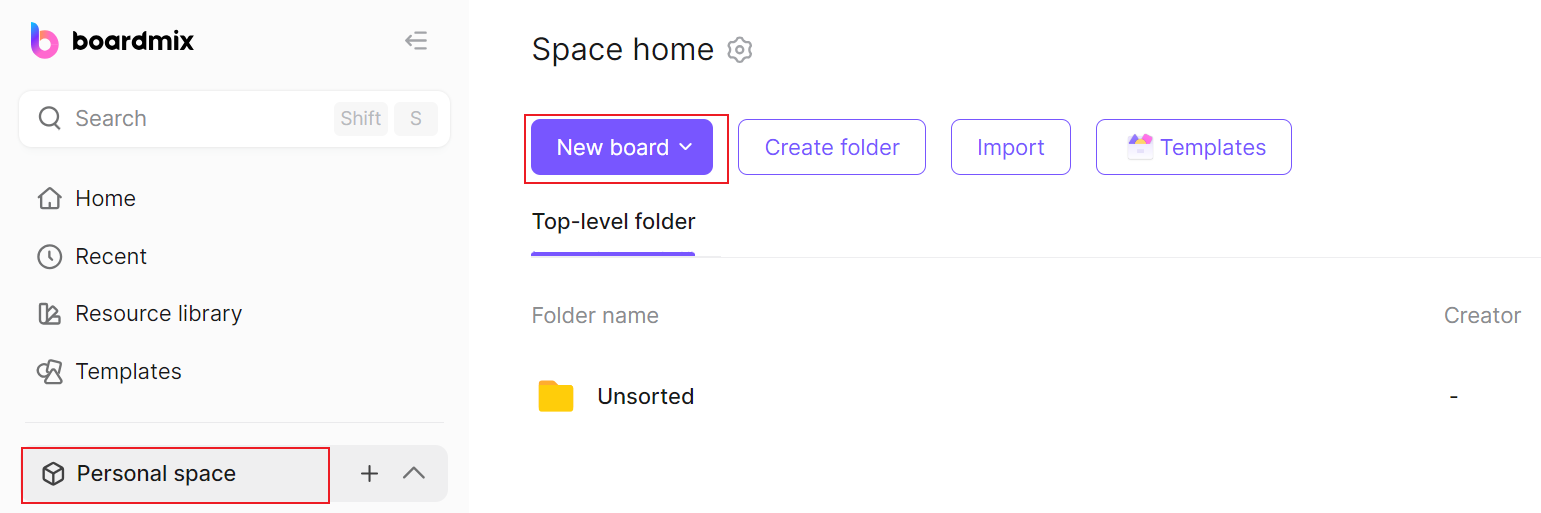
1. Login to Boardmix: Go to the Boardmix website and sign in to your account. If you don't have an account, you can create one for free.

2. Create a New Diagram: Click to start a New board. This will create a blank canvas for your network topology diagram. You also can go to the Template library and search for a topology template to save time.
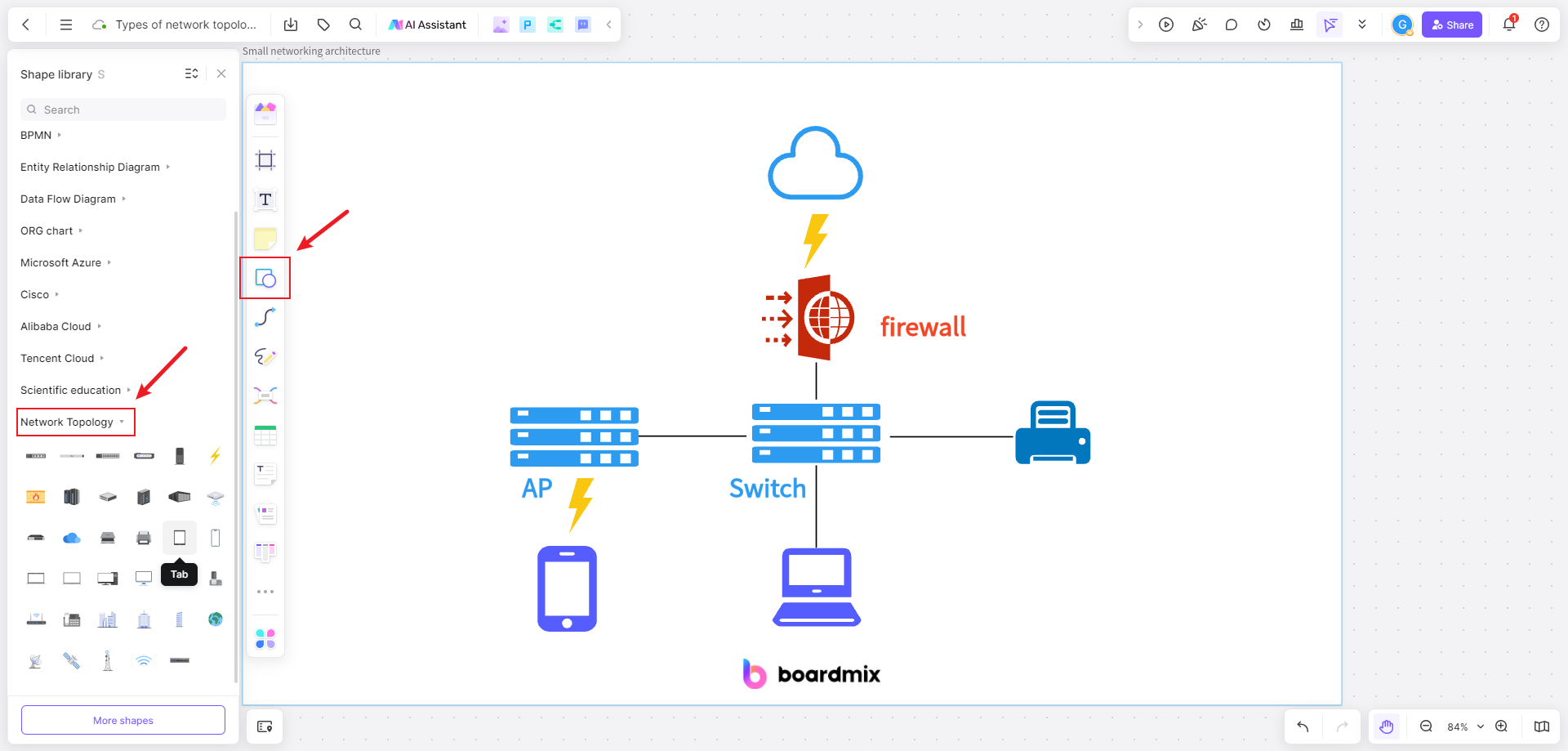
3. Add Devices: To start building your diagram, you need to add devices to represent the network components. Boardmix offers a wide range of device icons, such as routers, switches, firewalls, servers, and workstations. To add a device, simply drag and drop the desired icon onto the canvas.
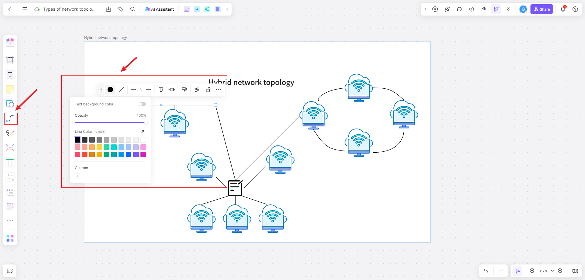
4. Connect Devices: After adding the devices, you need to connect them to illustrate the network connectivity. Boardmix provides customizable connection symbols for wired connections, wireless connections, and virtual connections. To create a connection, select the appropriate symbol and draw a line between the desired devices.
5. Customize Labels: To make your diagram more informative, you can add labels to devices, connections, and other elements. Labels can include IP addresses, subnet masks, interface details, or any other relevant information. To add a label, select the element and choose the "Label" option from the toolbar.
6. Arrange and Organize: Once you have added devices and connections, you can arrange and organize them to create a visually appealing layout. Boardmix offers an auto-layout feature that can automatically arrange the elements in a structured manner. Alternatively, you can manually adjust the position of each element by dragging them on the canvas.
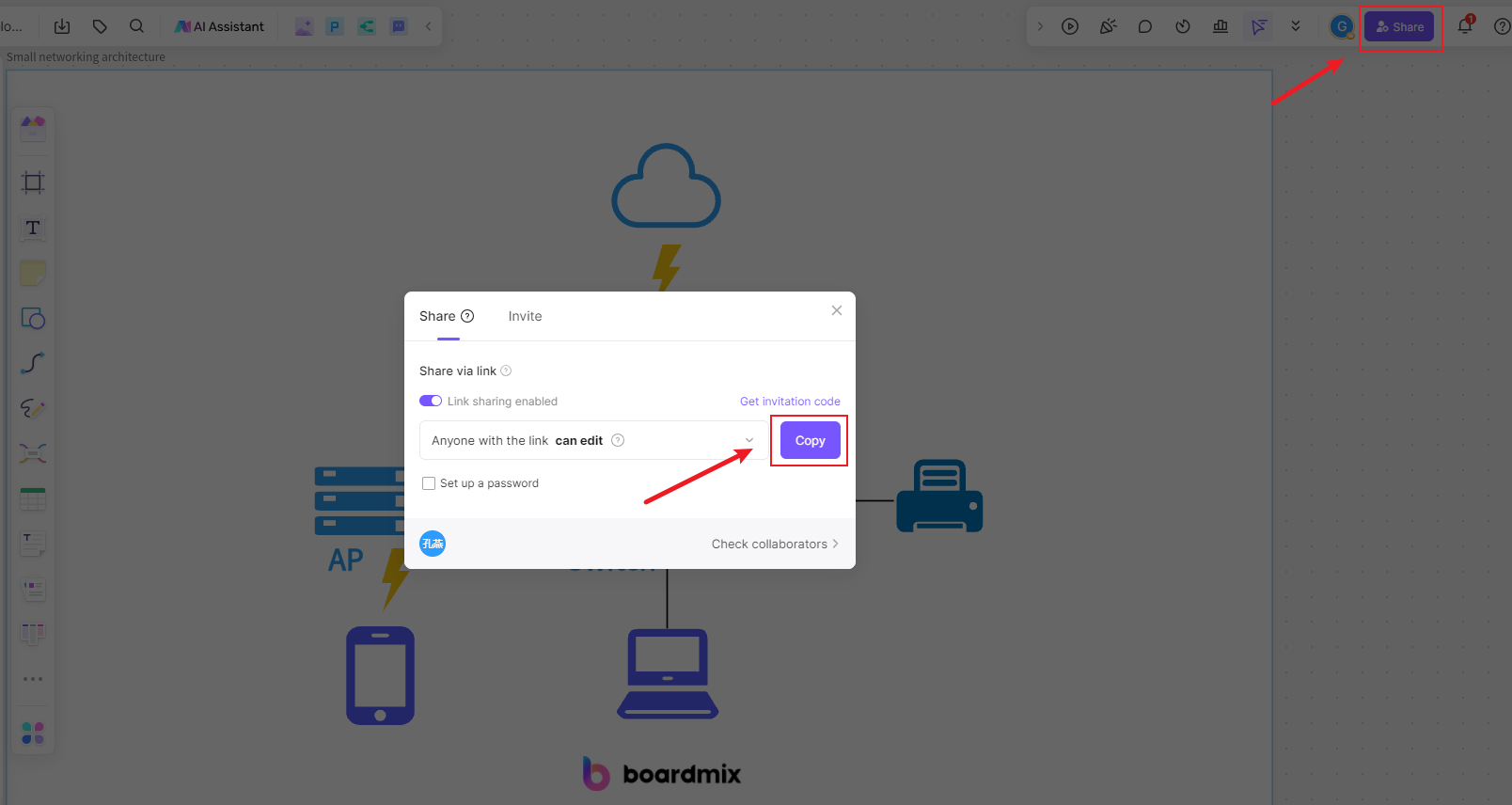
7. Collaborate and Share: Boardmix allows you to collaborate with team members or clients in real time. You can share your diagram with others by exporting it in various formats such as PDF, PNG, or SVG. You can also generate a shareable link or send it directly through email.
8. Save Your Diagram: Finally, don't forget to save your network topology diagram. Boardmix supports saving in its native format (.bm) for future editing. You can also save it in other common image formats for easy sharing and printing.
By following these steps, you can create a professional-looking network topology diagram using Boardmix. Feel free to explore additional features and functionalities offered by Boardmix to further enhance your diagram.
Industry Case Studies Network Topology Diagram
Diving into Industry Case Studies of Network Topology Diagrams can be likened to embarking on an expedition into the heart of real-world networking landscapes. It's about understanding the unique challenges each industry faces, the solutions they adopt, and the lessons they learn in the process. Here are some industry case studies of network topology diagram optimization.
Case Study 1: Company XYZ
Company XYZ is a multinational corporation with offices located in different countries. They faced challenges in managing their complex network infrastructure, as it consisted of numerous devices and connections. By optimizing their network topology diagram, they were able to streamline their network management processes and improve efficiency. They used color coding to differentiate between different office locations and labeled each device with its respective IP address. This allowed their IT team to quickly identify and troubleshoot any network issues.
Case Study 2: Healthcare Organization ABC
Healthcare Organization ABC required an optimized network topology diagram to ensure secure and reliable communication between various departments and medical devices. They used a hierarchical structure to group devices based on their functions, such as patient monitoring systems, electronic health record servers, and imaging equipment. This helped them visualize the network layout and identify any potential vulnerabilities. Additionally, they highlighted critical components such as firewalls and intrusion detection systems to ensure network security.
Case Study 3: E-commerce Company DEF
E-commerce Company DEF needed an optimized network topology diagram to support their high-traffic website and ensure seamless customer experience. They focused on scalability by designing the diagram to accommodate future growth in terms of website traffic and expanding their server infrastructure. They used color coding to differentiate between different types of servers, such as web servers, database servers, and load balancers. This helped them easily identify and manage their server resources.
These industry case studies demonstrate how optimizing network topology diagrams can greatly benefit organizations in terms of improved network management, enhanced security, and scalability. By implementing best practices such as hierarchical structures, color coding, and labeling, organizations can effectively represent their network infrastructure and ensure smooth operations.
Network Topology Diagram Optimization Examples
Optimizing a Network Topology Diagram can be compared to fine-tuning a musical instrument. It's about adjusting and rearranging the network elements in a way that ensures harmonious communication and peak performance. But this isn't just about moving nodes or changing connections. It's about understanding the principles of network design and applying them strategically to create an optimized network structure. Here are some examples of network topology diagram optimization.
- Minimize Network Complexity: One way to optimize a network topology diagram is to minimize complexity. This can be achieved by simplifying the connections between devices and reducing the number of unnecessary components. By eliminating redundant elements, the diagram becomes easier to understand and manage.
- Use Hierarchical Structure: Another optimization technique is to use a hierarchical structure in the diagram. This involves grouping devices based on their functions or locations. For example, routers and switches can be grouped in a separate section, while servers and workstations can be organized in another section. This hierarchical arrangement helps to visualize the network layout more clearly.
- Highlight Critical Components: In a network topology diagram, it is important to highlight critical components that play a crucial role in the network infrastructure. This can include firewalls, load balancers, or any other devices that are critical for ensuring network security and performance. By highlighting these components, it becomes easier to identify potential points of failure or bottlenecks.
- Use Color Coding and Labels: To make the diagram more informative, color coding and labels can be used to represent different types of devices or connections. For example, routers can be color-coded in blue, switches in green, and servers in red. Labels can also be added to provide additional information such as IP addresses or interface details. This visual representation helps to quickly identify different components and their functionalities.
- Consider Scalability: When creating a network topology diagram, it is important to consider scalability. This means designing the diagram in a way that allows for future growth and expansion. For example, if there is a possibility of adding more devices or increasing the network capacity, the diagram should accommodate these changes without becoming overly complex.
By following these optimization techniques, you can create a network topology diagram that is visually appealing, easy to understand, and effectively represents the network infrastructure. Remember to regularly update the diagram as the network evolves to ensure accuracy and relevancy.
To Recap
In conclusion, the creation and understanding of a Network Topology Diagram are fundamental in the world of system design and network management. Crafting a clear and comprehensive diagram becomes a cornerstone for mapping connectivity, optimizing performance, and ensuring the efficiency of network infrastructures.
As we explore Network Topology Diagram optimization examples, it becomes evident that the design and maintenance of a network are dynamic processes. Boardmix continues to be a valuable asset in adapting to changing network needs, ensuring that professionals have the tools they need to navigate and optimize complex network infrastructures effectively. Take action today and use Boardmix to decode and create Network Topology Diagrams that seamlessly map connectivity, ensuring the efficiency and reliability of your network infrastructure.