SDL diagrams describe system structure and behavior using Specification and Description Language. They help teams discuss how components communicate and respond to events. Define scope, identify components, establish relationships, select symbols, arrange elements, add details, review, save, and share. Tips include maintaining consistency, thoughtful color use, simplicity, collaboration, documentation, and regular updates. Boardmix can help teams draw and discuss a visual draft; formal SDL analysis requires a model and tools that support the language.
What Is an SDL Diagram
SDL stands for Specification and Description Language, standardized by ITU-T in the Z.100 series. It describes system structure and behavior through communicating state machines. SDL is used for reactive systems, including telecommunications protocols, where components respond to signals and change state.
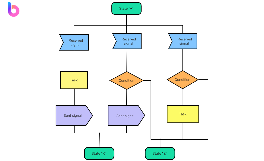
SDL diagrams break complex systems into components and show how those components interact. The drawing examples in this guide illustrate a visual drafting workflow. A sketch made with general diagram shapes is not automatically a formally valid SDL model.
When to Use an SDL Diagram
SDL diagrams serve as invaluable assets across the software development lifecycle, with distinct advantages in different phases.
Design Phase: During the initial design phase, architects and developers utilize SDL diagrams to conceptualize system structures. This step involves identifying potential bottlenecks, dependencies, and communication pathways, laying the foundation for a robust and efficient design.
Troubleshooting Phase: In the troubleshooting phase, SDL diagrams come to the forefront. Teams leverage them to pinpoint issues and streamline the debugging process, providing clarity in identifying and resolving problems.
Agile Collaboration Tool: Beyond specific phases, SDL diagrams prove versatile, adapting directly to different project stages. Their role extends to fostering effective communication across multidisciplinary teams, making them an indispensable tool in the collaborative landscape of software development.
Benefits of SDL Diagrams
SDL diagrams offer a myriad of benefits, starting with their ability to transcend language barriers and enhance communication. By providing a visual representation, they establish a shared understanding among diverse team members, fostering effective collaboration. Moreover, these diagrams streamline the design process, introducing a systematic and organized approach to system architecture. This not only enhances efficiency but also lays the groundwork for a more collaborative software development journey.
Diagrams can help teams review transitions and notice missing behavior. As ETSI explains, formal SDL analysis and simulation depend on models that follow the language rules and on suitable tools. Drawing a diagram in Boardmix alone does not establish that the model has been formally validated.
General Diagram Shapes Used in the Examples
The images below show general diagram shapes used in the drawing examples. They are not a complete SDL symbol reference. Each shape needs a defined meaning in its diagram; for a formal SDL model, follow the notation and semantics in the ITU-T Z.100 series.
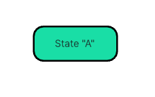
- State Shape:
- Symbol: Rectangle with rounded corners.
- Representation: The example labels this rounded rectangle as State "A".
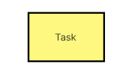
- Task Shape:
- Symbol: Rectangle.
- Representation: The example labels this rectangle as a task.
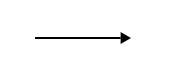
- Flow Arrow:
- Symbol: Arrow.
- Representation: Shows a direction between shapes. Label the connection to explain what it represents.
- Parallel Lines:
- Symbol: Two parallel vertical lines.
- Representation: An unlabelled pair of lines. This image does not establish a standard SDL storage symbol.

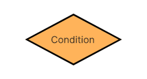
- Decision Diamond:
- Symbol: Diamond.
- Representation: Indicates a decision point in the system where the flow can take different paths.
- Hexagon:
- Symbol: Hexagon.
- Representation: A six-sided shape whose meaning must be stated in the diagram. It is not a generic SDL state symbol.

How to Make an SDL Diagram Using Boardmix
Boardmix, a collaborative whiteboard, can be used to draft and discuss a system diagram with shapes, text, and connectors. The steps below describe visual drafting, not SDL simulation or formal validation.

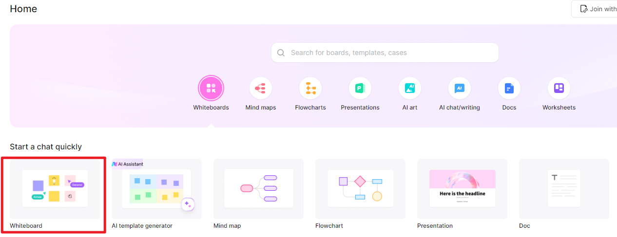
Login and Board Creation:
Commence by logging into Boardmix. Create a new board dedicated to organizing and structuring your SDL diagram.
Prepare the Labels:
Collect the state names, incoming and outgoing signals, and actions before drawing. Enter these labels as text on the board.
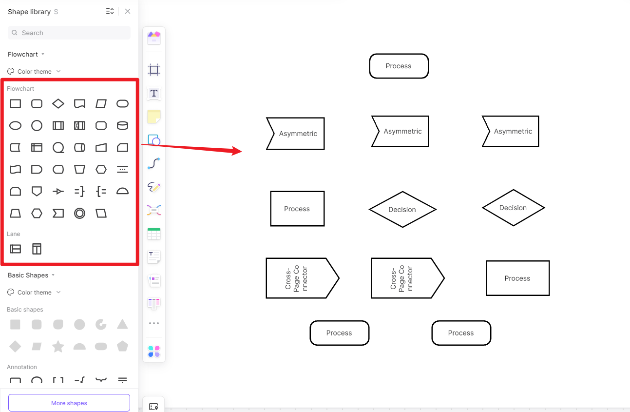
Block Creation:
Utilize the versatile tools provided by Boardmix to create blocks, symbolizing different components and functions within your SDL diagram.
Connection Lines:
Establish connections between blocks using lines. These lines illustrate the relationships and interactions between various components, providing a clear overview of your SDL diagram.
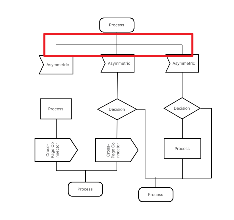
Customization:
Leverage Boardmix's diverse customization options to modify colors, labels, and other details. Tailor your SDL diagram to align with your preferences, ensuring a visually coherent and informative representation.
Finalization:
Review the diagram on the board. Check labels, arrow directions, and connections, then refine any unclear parts before sharing.
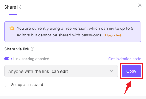
Share Your Board:
Once satisfied with your diagram, share the board with your team. Use Boardmix's collaboration features to discuss the draft and refine it together.
Embark on your SDL diagram creation journey with Boardmix, where the absence of a specific template is not a hindrance but rather an opportunity for connected and effective visualization of system specifications and descriptions.
Tips and Tricks on Making an SDL Diagram
Creating SDL (Specification and Description Language) diagrams is a nuanced process that demands precision and clarity. Elevate your diagramming prowess with these comprehensive tips, delving into each aspect for a more effective and logically clear SDL diagram:
- Consistency is Key: Maintain consistency in the use of symbols and notations throughout the diagram for clarity and coherence.
- Use Colors Thoughtfully: Employ colors to highlight different elements or to emphasize specific relationships, enhancing visual appeal.
- Keep It Simple: Avoid unnecessary complexity. A clear and concise SDL diagram is more effective in conveying information.
- Collaborate and Seek Feedback: Involve team members in the diagramming process to benefit from diverse perspectives. Seek feedback to refine and improve the diagram.
- Document Assumptions and Constraints: Clearly document any assumptions or constraints considered during the diagram creation to provide context for future reference.
- Update Regularly: As the system evolves, update the SDL diagram to reflect changes accurately, ensuring it remains a relevant and reliable reference tool.
By meticulously adhering to these tips and strategies, users can optimize the SDL diagram creation process. The result is a set of SDL diagrams that not only encapsulate comprehensive information but are also easily understandable for all stakeholders involved in the intricate dance of the software development lifecycle.