Class diagrams are fundamental to object-oriented modeling and are crucial for visualizing and designing complex systems. As a core component of the Unified Modeling Language (UML), class diagrams provide a structured representation of the system's classes, attributes, operations, and relationships among objects. The article will differentiate between UML and class diagrams, and explain how to use class diagrams in software development effectively.
What are the Principles of Class Diagram?
Class diagrams are guided by several fundamental principles that ensure they effectively represent the system's structure and behavior. Here are the key principles:
1. Encapsulation
Encapsulation refers to bundling the data (attributes) and methods (operations) that operate on the data into a single unit, or class. This principle ensures that the internal state of an object is hidden from the outside, exposing only the necessary functionalities.
2. Inheritance
Inheritance allows a class to inherit attributes and operations from another class, promoting code reuse and establishing a hierarchy. This relationship is depicted in class diagrams using a solid line with a closed, hollow arrowhead pointing towards the superclass.
3. Polymorphism
Polymorphism enables objects to be treated as instances of their parent class rather than their actual class. This principle supports method overriding, where a subclass can provide a specific implementation of a method that is already defined in its superclass.
4. Association
The association represents the relationship between the two classes. This can include multiplicities to specify how many instances of one class can be associated with instances of another class. For example, a one-to-many association between a Library and Books.
5. Aggregation and Composition
Aggregation is a type of association that represents a "whole-part" relationship between the aggregate (whole) and a part. Composition is a stronger form of aggregation indicating that the whole manages the lifecycle of the part.
6. Dependency
Dependency indicates a relationship where one class depends on another because it uses it in some capacity. This is depicted with a dashed line and an arrow.
Why Use the Class Diagram?
Class diagrams are extensively used in software engineering due to their numerous benefits:
1. Visual Representation
The class diagram provides a visual representation of the system’s static structure, making it easier to understand and communicate complex designs.
2. Blueprint for Development
They serve as a blueprint for constructing the system, offering detailed insights into the system’s components and their interactions, which guide developers during the implementation phase.
3. Improved Communication
Class diagram enhances communication among team members and stakeholders by providing a clear and consistent visual language. This is especially useful for conveying design decisions and ensuring everyone is on the same page.
4. Facilitates Maintenance and Scalability
By clearly outlining the system’s architecture, class diagrams facilitate easier maintenance and scalability. They help identify potential issues and dependencies that could impact future changes or expansions.
Class Diagram Examples
To illustrate the practical application of class diagrams, let's consider a few examples:
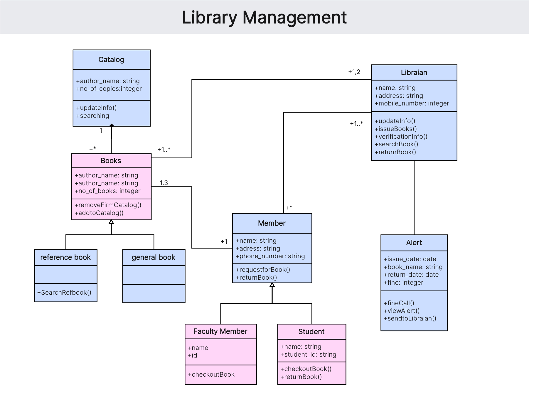
1. Library Management System Class Diagram
A class diagram for a Library Management System might include classes like Library, Book, Member, and Staff. The Library class aggregates multiple Book instances, and associations are shown between the Library and Members, as well as the Library and Staff.
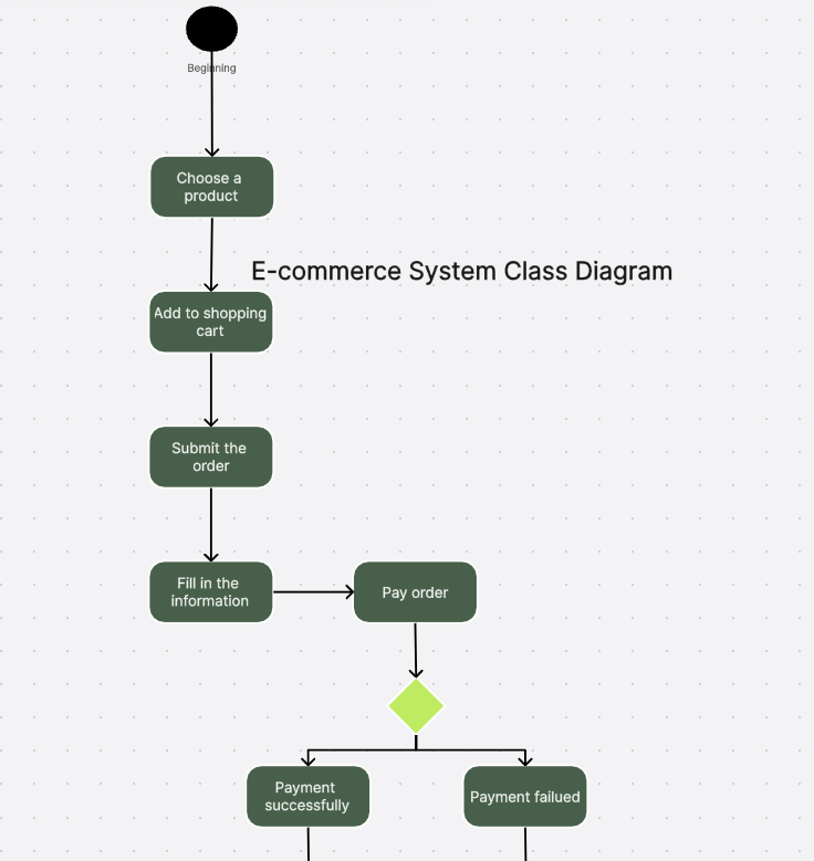
2. E-commerce System Class Diagram
In an e-commerce system, you might have classes such as Customer, Order, Product, and Payment. The Customer class can have an association with Order, while Order aggregates multiple Product instances. The Payment class is associated with Order.
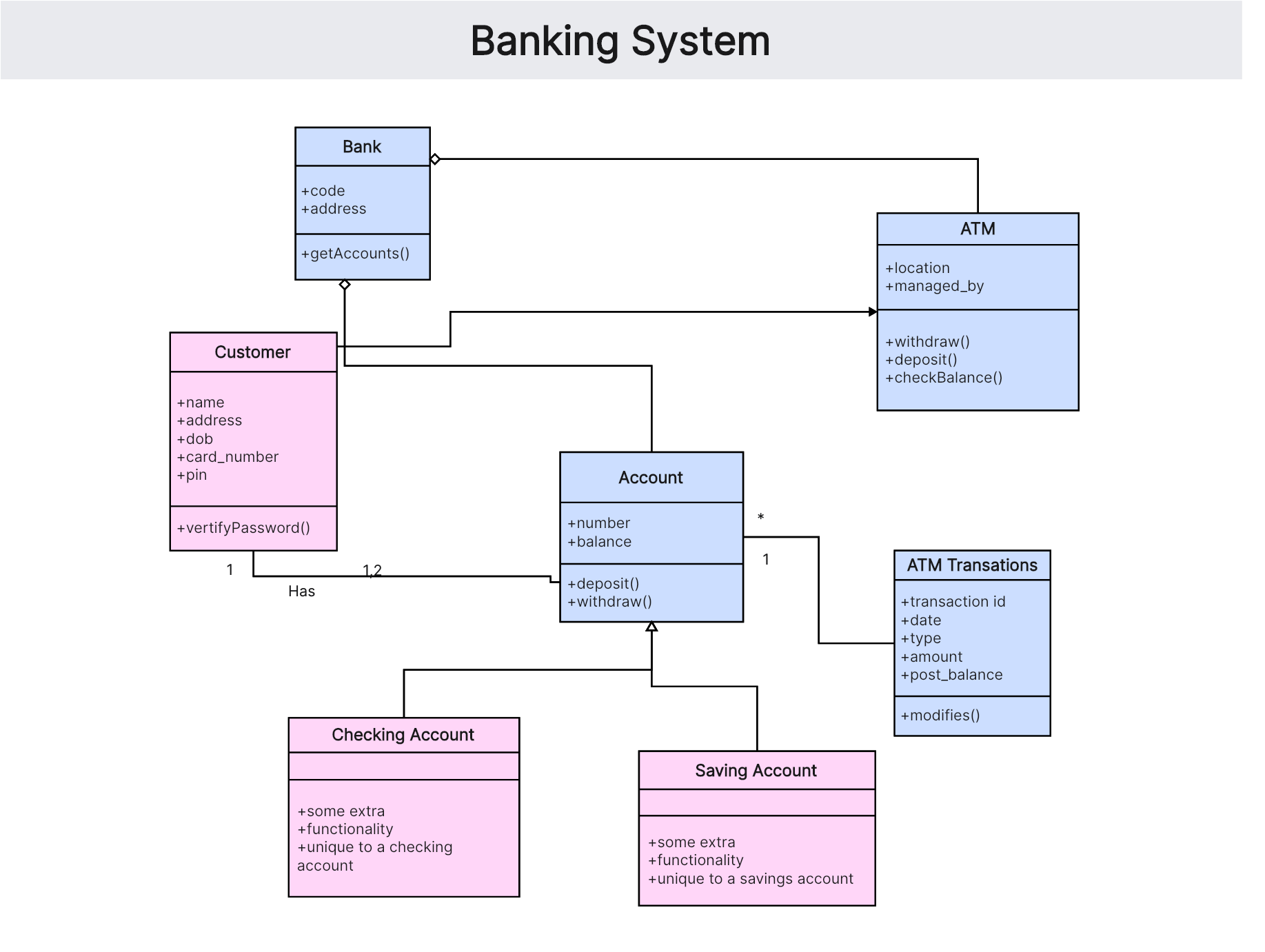
3. Banking System Class Diagram
A banking system might include classes such as Bank, Account, Transaction, and Customer. The Bank class aggregates multiple Account instances, and each Account is associated with multiple Transaction instances. The Customer class is linked to the Account class.
4. School Management System Class Diagram
A class diagram for a School Management System might include classes like School, Student, Teacher, and Course. The School class aggregates multiple Course instances, and associations are shown between School and Student, as well as School and Teacher.
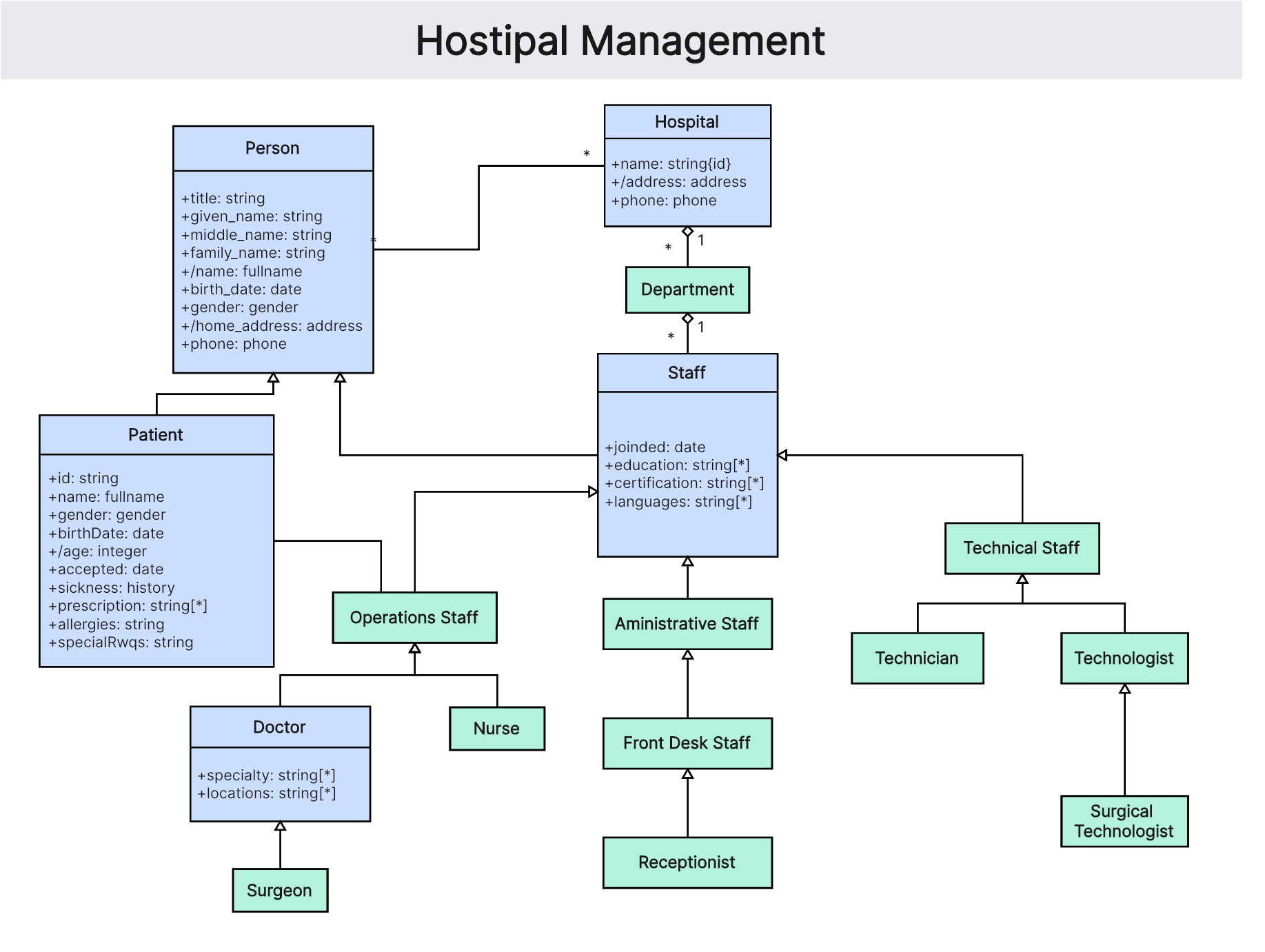
5. Healthcare Management System Class Diagram
A class diagram for a Healthcare Management System might include classes like Hospital, Patient, Doctor, and Appointment. The Hospital class aggregates multiple Doctor and Patient instances, and associations are shown between Patient and Appointment, as well as Doctor and Appointment.
6. Online Learning Platform Class Diagram
A class diagram for an Online Learning Platform might include classes like Platform, User, Course, and Enrollment. The Platform class aggregates multiple Course instances, and associations are shown between User and Enrollment, as well as Course and Enrollment.
What is the Difference between UML and Class Diagram?
While the terms UML and class diagram are often used interchangeably, they refer to different concepts within the realm of software modeling and design. Here’s a detailed comparison to highlight their differences and specific roles in software development:
1. Unified Modeling Language (UML)
Unified Modeling Language (UML) is a standardized modeling language developed by the Object Management Group (OMG). It provides a general-purpose visual language for specifying, visualizing, constructing, and documenting the artifacts of a software system. UML helps in understanding, designing, and managing complex software systems through a variety of diagram types that represent different aspects of the system.
2. Class Diagram
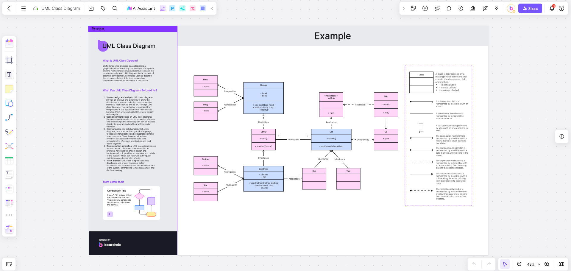
A class diagram is one of the many types of diagrams offered by UML. It specifically focuses on representing the static structure of a system, showing the system's classes, attributes, operations (or methods), and the relationships among the classes. Class diagrams are central to object-oriented modeling and are used to describe the types of objects in the system and the various static relationships that exist among them.
Comparison🎇🎇🎇:
|
FEATURES |
UML |
CLASS DIAGRAM |
| Scope | Broad; encompasses various types of diagrams | Broad; encompasses various types of diagrams |
| Purpose | General-purpose modeling language | Represents static structure of classes |
| Diagram Types | Multiple (e.g., use case, sequence, activity) | Single type |
| Usage | Used for diverse modeling needs | Used for object-oriented design |
| Notation | A comprehensive set of symbols for various diagrams | Symbols specific to classes and relationships |
Understanding the distinction between UML and class diagrams is crucial for effectively utilizing these tools in software development, ensuring clear and precise communication of system designs and structures.
How to Explain Class Diagram?
Explaining class diagrams involves breaking down their components and relationships clearly and understandably. Here’s a step-by-step approach:
1. Identify the Classes
Start by identifying the main classes that represent the key entities in the system. Each class should have a name that indicates its role.
2. Define Attributes and Operations
For each class, list the attributes (data fields) and operations (methods) that define its properties and behavior. Ensure that these are relevant to the class's responsibilities.
3. Establish Relationships
Identify the relationships between the classes, such as associations, inheritance, and dependencies. Use appropriate notations to represent these relationships.
4. Use UML Notations
Apply UML notations to ensure consistency and standardization. Use rectangles for classes, lines for associations, and arrows for inheritance and dependencies.
5. Add Multiplicities
Specify multiplicities to indicate how many instances of a class can be associated with instances of another class. This helps in understanding the cardinality of relationships.
6. Include Aggregation and Composition
Distinguish between aggregation and composition to represent "whole-part" relationships accurately. Use hollow diamonds for aggregation and filled diamonds for composition.
Class diagrams are a powerful tool in the realm of software development, providing a clear and structured way to visualize and design systems. By adhering to the principles of encapsulation, inheritance, polymorphism, association, aggregation, and dependency, class diagrams offer a comprehensive representation of a system's static structure. They not only facilitate better communication and understanding among stakeholders but also serve as a blueprint for implementation and a valuable documentation resource. Understanding the distinction between UML and class diagrams, and knowing how to effectively explain and use class diagrams, is essential for any software engineer looking to create robust and scalable systems.