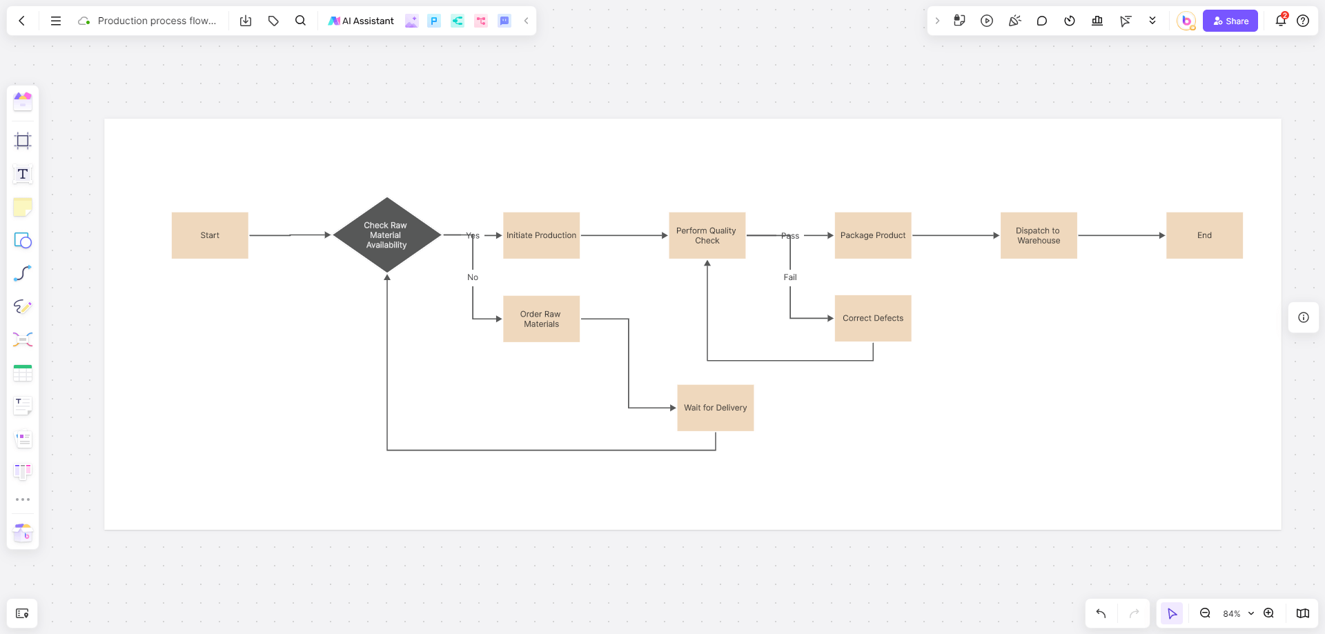
Flowcharts have revolutionized the way we visualize complex systems. When it comes to electrical systems, an electricity flowchart with voltages becomes essential for understanding, troubleshooting, and designing circuits. But how do you create an effective flowchart? This guide will break it down step by step, ensuring clarity and accuracy in every process.
What is Electricity Flowchart with Voltages?
An electricity flowchart is a graphical representation of electrical processes, showing the flow of current, voltage points, and components within a system. These diagrams are commonly used to:
- Illustrate the structure of electrical circuits.
- Highlight voltage levels across components like resistors, capacitors, and inductors.
- Provide a clear sequence of operations for troubleshooting.
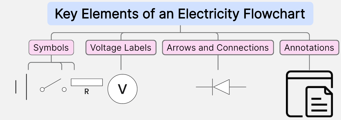
Key Elements of an Electricity Flowchart:
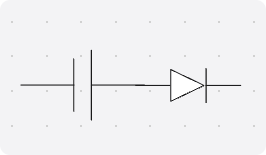
- Symbols: Represent components such as switches, resistors, or power sources.
- Voltage Labels: Indicate critical voltage points for analysis.
- Arrows and Connections: Show the direction of current and logical flow.
- Annotations: Offer clarity about measurements, thresholds, and operating conditions.
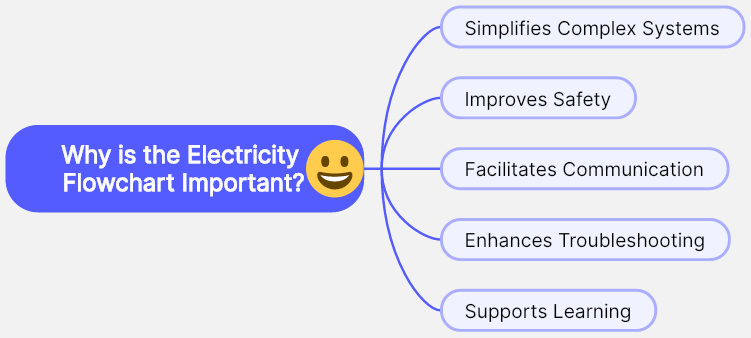
Why is the Electricity Flowchart Important?
An electricity flowchart is more than a visual aid. It’s a practical tool with significant benefits:
- Simplifies Complex Systems: Breaks down intricate circuits into manageable visual elements.
- Improves Safety: By detailing voltage points and flow, it reduces risks during repairs or installation.
- Facilitates Communication: Engineers, electricians, and stakeholders can collaborate more effectively with a shared diagram.
- Enhances Troubleshooting: Pinpoints faults quickly by mapping the entire process step by step.
- Supports Learning: For students and professionals, it provides a foundation for understanding circuit behavior.
Steps in Measuring Voltage Flowchart: Diagnose Voltage Issues in a Simple Circuit
The following steps guide users through diagnosing voltage issues in a simple circuit. This process ensures accurate troubleshooting and resolution by systematically following, testing, and verifying components and connections.

Step 1: Begin Diagnosis
Node: Start the diagnosis process.
Action: Ensure the circuit is powered off to prevent accidental shocks.
Step 2: Inspect Physical Connections
Node: Are all wires and components securely connected?
Action:
- Check for loose wires, frayed cables, or disconnected components.
- Tighten or replace faulty connections.
Decision:
- If all connections are secure, proceed.
- If issues are found, fix and restart the diagnosis.
Step 3: Verify Power Source
Node: Test the voltage of the power source (e.g., battery or power supply).
Action:
- Use a multimeter to measure voltage across the terminals.
- Compare the reading to the expected value (e.g., 9V, 12V).
Decision:
- If voltage is correct, proceed to the next step.
- If voltage is incorrect, replace or recharge the power source.
Step 4: Check Switch Operation
Node: Is the switch functioning correctly?
Action:
- Test the switch for continuity with a multimeter.
- Ensure it closes the circuit when toggled on.
Decision:
- If the switch works, continue to the next step.
- If the switch is faulty, replace it and restart testing.
Step 5: Measure Voltage Across Components
Node: Measure voltage at each component (e.g., resistor, LED).
Action:
- Place multimeter probes across the component.
- Record and compare the measured voltage to the expected value.
Decision:
- If the voltage matches, the component is functioning correctly.
- If voltage differs, inspect or replace the component.
Step 6: Test Current Flow
Node: Check if current flows through the circuit.
Action:
- Set the multimeter to measure current.
- Connect it in series with the circuit.
Decision:
- If current flows as expected, proceed to the next step.
- If no current flows, revisit previous nodes to identify faults.
Step 7: Inspect Grounding
Node: Is the circuit properly grounded?
Action:
- Verify all ground connections are intact.
- Ensure grounding points are free of rust or debris.
Decision:
- If grounding is intact, continue.
- If issues are found, clean or reconnect the ground points.
Step 8: Final Test
Node: Conduct a full circuit test.
Action:
- Power the circuit and measure voltage at all key points.
- Confirm proper functionality of all components.
Decision:
- If the circuit operates correctly, conclude the diagnosis.
- If issues persist, repeat steps or seek expert assistance.
The above steps show how to diagnose voltage issues in a simple circuit. Use tools like Boardmix to create a flowchart of these steps for clear visualization and effective team communication.
How to Draw Electricity Flowchart with Voltages on Boardmix
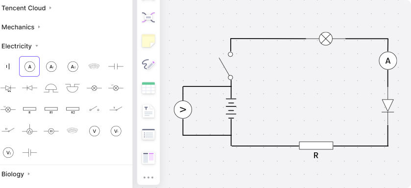
Using Boardmix, an online whiteboard tool, makes creating an electricity flowchart seamless. With its user-friendly interface and powerful features, it’s the best program for diagrams in electrical applications.
Step 1: Access the Template Library
- Log into Boardmix and search for pre-designed templates like circuit diagrams or voltage flowcharts.

Step 2: Add Core Elements
- Drag and drop essential symbols from the library (e.g., power sources, resistors, or voltage points).
- Use color-coded voltage labels to distinguish different levels.
Step 3: Define Flow and Connections
- Draw arrows to represent the direction of current flow.
- Connect all components logically to ensure accuracy.
Step 4: Annotate Voltage Points
- Add voltage measurements or thresholds at critical nodes.
- Use Boardmix's annotation tools to include notes or alerts.
Step 5: Collaborate and Review
- Share the flowchart with team members for feedback.
- Use real-time collaboration to refine and update diagrams.

Step 6: Export and Share
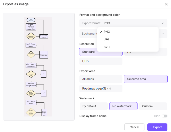
- Save your flowchart in formats like PDF or PNG for easy sharing with colleagues or stakeholders.
FAQs About Electricity Flowcharts
- What is an electricity flowchart, and why is it important?
An electricity flowchart visually represents electrical processes, such as current flow or circuit design. It simplifies complex systems, making troubleshooting and communication easier for engineers and technicians.
- How does an electricity flowchart with voltages help diagnose issues?
It identifies voltage points across a circuit, highlighting discrepancies from expected values. This allows users to locate faults like broken connections, faulty components, or grounding issues.
- What tools are commonly used to draw electricity flowcharts?
Tools like Boardmix, Visio, and Lucidchart offer easy-to-use interfaces for designing flowcharts. They provide customizable templates, drag-and-drop features, and collaboration options to streamline the process.
- Can electricity flowcharts be used for education?
Yes, they are ideal for teaching basic and advanced electrical concepts. Visual aids like flowcharts simplify explanations of circuit behavior, voltage distribution, and safety protocols for students and trainees.
Final Thoughts
An electricity flowchart with voltages is a vital tool for engineers, electricians, and learners alike. By using a platform like Boardmix, creating these diagrams becomes intuitive and efficient. From simplifying complex circuits to facilitating collaboration, the benefits are undeniable. Ready to enhance your workflow? Start crafting professional-grade electricity flowcharts with Boardmix today.


