In the realm of system design and architecture, a crucial element that plays a pivotal role in conveying the structural components and relationships within a system is the physical architecture diagram. This visual representation provides a comprehensive overview of the hardware elements and their interconnections, offering invaluable insights into the physical infrastructure of a system. In this article, we will delve into the importance of physical architecture diagrams, their key components, and how they contribute to effective system development.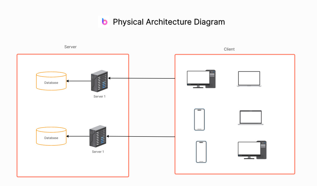
Part 1. The Essence of Physical Architecture Diagrams
A physical architecture diagram serves as a blueprint that illustrates the physical layout of a system. Unlike other architectural diagrams that focus on software components and their interactions, the physical architecture diagram primarily emphasizes the tangible, hardware aspects of a system. This includes servers, networks, storage devices, and other physical elements that collectively form the foundation of a robust system.
Part 2. Key Components of a Physical Architecture Diagram
A physical architecture diagram provides a visual representation of the physical components and their interactions within a system or network. The key components of a physical architecture diagram typically include:
- Hardware Components: The central aspect of a physical architecture diagram revolves around hardware components. This encompasses servers, routers, switches, storage devices, and any other physical entities that contribute to the system's functionality. Each hardware component is typically represented by a distinct symbol or shape for clarity.
- Connections and Networks: The diagram illustrates the connections between various hardware components, emphasizing the network architecture. This includes the physical links between servers, the layout of network switches, and the pathways through which data flows. Network topology, such as star, bus, or mesh configurations, is often highlighted.
- Data Flow and Storage: Physical architecture diagrams also showcase the flow of data between different components. This involves detailing how data is processed, stored, and transmitted within the system. Storage solutions like databases and disk arrays are visualized, indicating the locations where data is stored and retrieved.
- Environmental Considerations: Physical architecture diagrams may include environmental factors such as data centers, server rooms, and cooling systems. These elements are critical to ensuring the optimal functioning of hardware components and are therefore essential to the overall system design.
The specific components and level of detail in a physical architecture diagram can vary depending on the complexity of the system and the intended audience. The goal is to provide a clear and comprehensive overview of the physical infrastructure supporting a system or network.
Part 3. Benefits of Physical Architecture Diagrams
Physical architecture diagrams offer several benefits in understanding, designing, and managing complex systems or networks. Some of the key advantages include:
Visualization:
- Clarity: Diagrams provide a visual representation of the physical components and their relationships, making it easier to understand the overall architecture.
- Complexity Management: Helps manage the complexity of large-scale systems by breaking them down into understandable components.
Communication:
- Common Understanding: Facilitates communication among stakeholders, ensuring that everyone involved in the project has a common understanding of the physical infrastructure.
- Documentation: Serves as a visual documentation tool, making it easier for teams to discuss, review, and update the system architecture.
Design and Planning:
- System Design: Aids in the design phase by allowing architects and engineers to plan and visualize the arrangement of physical components.
- Resource Allocation: Helps in allocating resources effectively by identifying bottlenecks, optimizing hardware placement, and planning for scalability.
Troubleshooting and Maintenance:
- Issue Identification: Simplifies troubleshooting by providing a clear map of the physical components, making it easier to identify and locate potential issues.
- Maintenance Planning: Supports maintenance activities by visualizing the relationships between components and helping teams plan for updates, replacements, or expansions.
Resource Optimization:
- Efficient Resource Usage: Helps in optimizing the use of physical resources such as servers, storage, and network devices.
- Cost Management: Supports cost-effective decision-making by providing insights into the physical infrastructure's layout and resource utilization.
Collaboration:
- Collaborative Planning: Facilitates collaboration among different teams (e.g., development, operations, security) by providing a shared view of the physical architecture.
- Interdisciplinary Understanding: Helps teams with different expertise understand how their work relates to the broader physical infrastructure.
Physical architecture diagrams are valuable tools that contribute to effective communication, planning, troubleshooting, and decision-making throughout the lifecycle of a system or network.
Part 4. How Do You Make a Physical Architecture Diagram?
Creating a physical architecture diagram involves several steps to ensure a comprehensive and accurate representation of the system's hardware components and their relationships. Here's a guide on how to make a physical architecture diagram: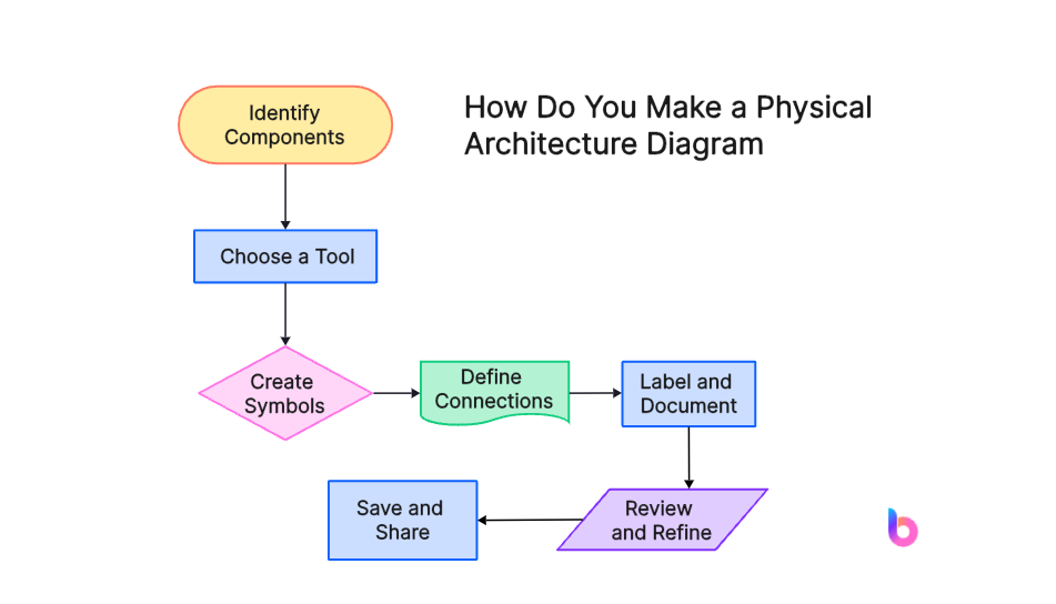
Step 1. Identify Components: List all hardware components in your system, like servers, routers, and storage devices.
Step 2. Choose a Tool: Select a diagramming tool such as Visio, draw.io, or pen and paper.
Step 3. Create Symbols: Familiarize yourself with symbols for different components and start placing them on your diagram.
Step 4. Define Connections: Map out the physical connections between components, showing network pathways.
Step 5. Label and Document: Label each component for identification and include details. Document critical information.
Step 6. Review and Refine: Double-check for accuracy and completeness. Get feedback and refine as needed.
Step 7. Save and Share: Save the diagram in a common format and share it with relevant stakeholders for collaboration and future reference.
By following these steps, you can create a clear and informative physical architecture diagram that serves as a valuable reference for system design, communication, and troubleshooting.
Part 5. What Is the Difference Between Logical Architecture Diagram and Physical Architecture Diagram?
The logical architecture diagram and the physical architecture diagram serve distinct purposes in system design, focusing on different aspects of a system.
The logical architecture diagram emphasizes the abstract, conceptual view of a system, illustrating the relationships and interactions between software components. Operating at a higher level of abstraction, it outlines the system's functionalities without delving into hardware specifics. In contrast, the physical architecture diagram provides a detailed, tangible representation of the system's physical infrastructure. Focused on the actual hardware components, their placements, and interconnections, it aids in understanding the system's concrete implementation. While the logical diagram is crucial for planning software architecture and functionality, the physical diagram is essential for addressing hardware-related issues, offering an overview of servers, networks, and storage. Together, these diagrams provide a comprehensive understanding of a system from both abstract and tangible perspectives.
Part 6. Use Boardmix to Make a Physical Architecture Diagram
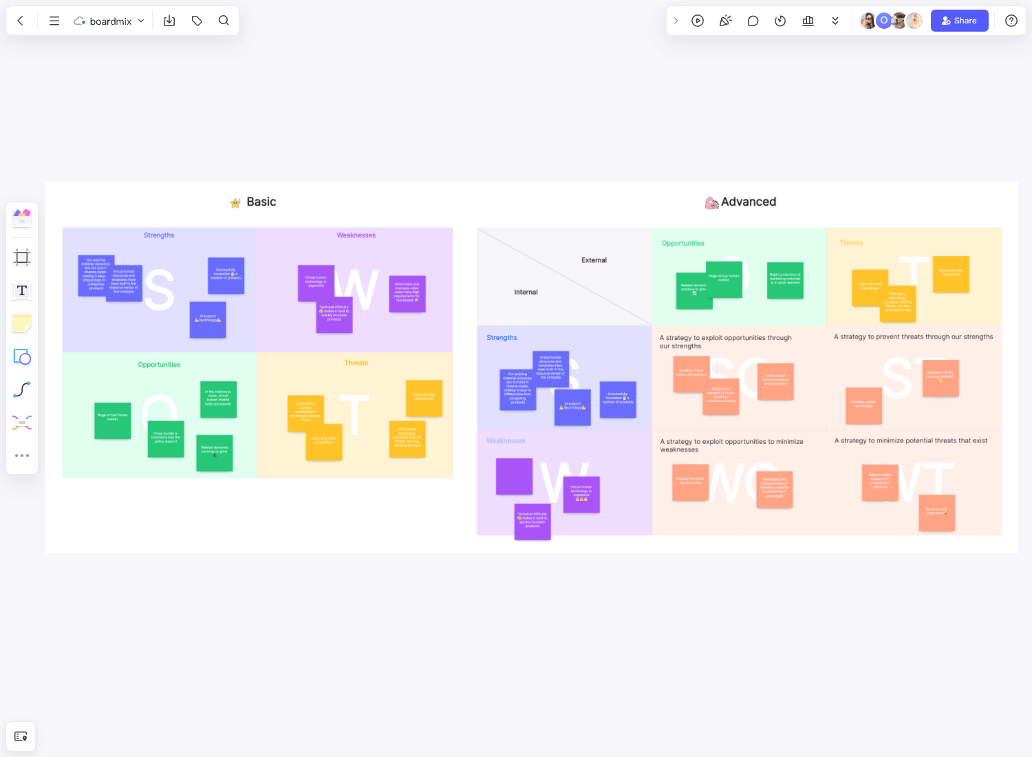
Boardmix is an innovative online whiteboard solution designed to revolutionize the way you create and share physical architecture diagrams. With a vast array of intuitive drawing templates at your disposal, Boardmix makes it incredibly easy to visualize complex architectural structures, facilitating better understanding and collaboration among teams. Whether you're sketching out a new building design or mapping out an IT network infrastructure, Boardmix's user-friendly interface and powerful tools enable you to bring your ideas to life with precision and ease. Unlike traditional methods, Boardmix allows for real-time updates and seamless sharing capabilities, ensuring everyone on your team stays in sync no matter where they are.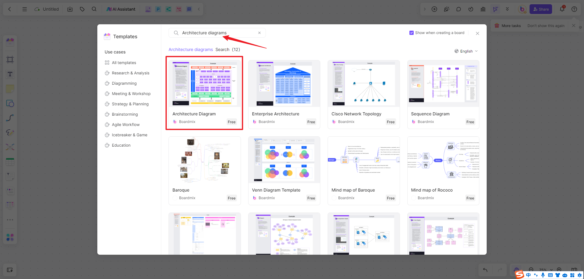
Conclusion
In the intricate landscape of system design, the importance of physical architecture diagrams cannot be overstated. These visual representations not only provide a roadmap for system architects and engineers but also serve as a vital tool for effective communication and problem-solving. By capturing the physical essence of a system, these diagrams contribute significantly to the success of complex projects and the seamless operation of modern technological infrastructures.
Moreover, Boardmix is the best architecture diagramming tool that can help you create a physical architecture diagram. Start with the free trial now!