Designing a Logical Network Topology diagram online can be compared to drafting a blueprint for a virtual city. But this isn't just about drawing lines between nodes. It's about utilizing the right online tools that allow you to design an accurate and comprehensive logical network. So, how do you design this topology online? What tools are available to assist you in this process? Let's delve into these questions together, navigating the world of Logical Network Topology design in the online realm.
What is Logical Network Topology?
Logical network topology refers to how data is transmitted within a network. It represents the logical connections and pathways between network devices, such as routers, switches, and servers. Unlike physical network topology, which describes the physical layout of network devices and cables, logical network topology focuses on how data flows through the network.
In a logical network topology, devices are connected based on logical relationships, such as the network protocol being used or the type of data being transmitted. For example, in a star topology, all devices are connected to a central hub or switch. In a ring topology, data flows in a circular path from one device to the next. In a mesh topology, devices are interconnected with multiple paths for redundancy.
Logical network topologies are designed to optimize data transmission, ensure reliable connectivity, and provide scalability. They help network administrators understand how data flows through the network and troubleshoot any issues that may arise. By understanding the logical network topology diagram, administrators can make informed decisions about network configuration, bandwidth allocation, and security measures.
Overall, logical network topology is essential for efficient and effective data transmission within a network. It provides a framework for organizing and managing network resources, ensuring smooth communication between devices, and facilitating the sharing of information.
Types of Logical Network Topology
There are several types of logical network topologies, each with its advantages and disadvantages. Some common types include:
- Star Topology: In a star topology, all devices are connected to a central hub or switch. This central hub acts as a central point of communication, and all data flows through it. This topology is easy to set up and allows for easy troubleshooting, as any issues with a specific device can be isolated without affecting the rest of the network. However, it relies heavily on the central hub, so if it fails, the entire network may be affected.
- Ring Topology: In a ring topology, devices are connected in a circular path, with each device connected to two neighboring devices. Data flows in one direction around the ring. This topology is simple and efficient, as each device only needs to transmit data to its neighbors. However, if one device fails or a cable is disconnected, the entire network may be affected.
- Bus Topology: In a bus topology, all devices are connected to a common communication line, called a bus. Data is transmitted along this bus and can be received by any device connected to it. This topology is easy to set up and cost-effective for small networks. However, if the bus fails, the entire network may be affected.
- Mesh Topology: In a mesh topology, devices are interconnected with multiple paths for redundancy. This means that if one path fails, data can still be transmitted through an alternate path. Mesh topologies can be full mesh, where every device is directly connected to every other device, or partial mesh, where only certain devices have multiple connections. This topology provides high reliability and fault tolerance but requires more cabling and is more complex to manage.
These are just a few examples of logical network topologies. The choice of topology depends on factors such as the size of the network, the required level of redundancy, and the type of data being transmitted. Network administrators need to carefully consider these factors when designing a network topology to ensure efficient and reliable data transmission.
Logical Network Topology Application Examples
In practical applications, different logical network topologies are suitable for different scenarios. Here are some examples of logical network topologies in applications.
- Star Topology: Star topology is suitable for small home networks and small office networks. In these scenarios, the central hub or switch serves as the center of the network, connecting all devices. This topology is easy to set up and troubleshoot, making it very suitable for beginners or non-technical personnel. However, if the central hub fails, the entire network may be affected.
- Ring Topology: Ring topology is often used in local area networks (LANs). In this topology, devices are connected in a ring path and data is transmitted in one direction along the ring path. Ring topology provides high reliability and fault tolerance; even if a device fails or a cable breaks, data can still flow. Therefore, this topology is common in scenarios that require high reliability, such as financial institutions or medical institutions.
- Bus Topology: Bus topology is commonly used in small networks such as small offices or home networks. In bus topology, all devices are connected to a shared communication bus and data is transmitted along the bus. This topology is simple and affordable, suitable for scenarios with low network requirements. However, if the bus fails, the entire network may be affected.
- Mesh Topology: Mesh topology applies to large networks or scenarios with high-reliability requirements. In mesh topology, devices interconnect through multiple paths providing redundancy and fault tolerance; if one path fails data can still be transmitted via alternative paths this structure offers high reliability/redundancy but requires more wiring/management.
These are some examples of logical network topologies in practical applications choosing a suitable topology for specific scenarios requires careful consideration by network administrators to ensure efficient and reliable transmission.
How to Design Logical Network Topology in Boardmix?
Steps to Create a Network Topology Diagram in Boardmix
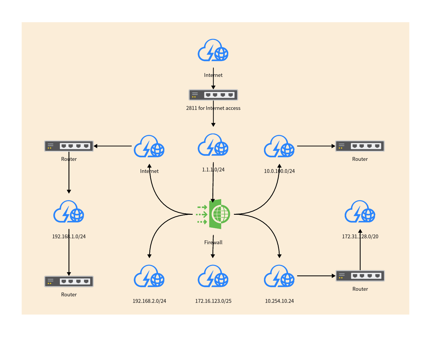
A logical network topology diagram is a graphical representation that displays the structure of a network, including its nodes and connections. It has wide applications on many occasions such as IT management, project planning, or education. Below, we will guide you on how to create a logical network topology diagram in Boardmix.
1. Log into Boardmix
Firstly, you need to navigate to the Boardmix webpage and log into your Boardmix account. If you haven't registered yet, please register for a Boardmix account using your email.

2. Create a New Project or Choose a Template
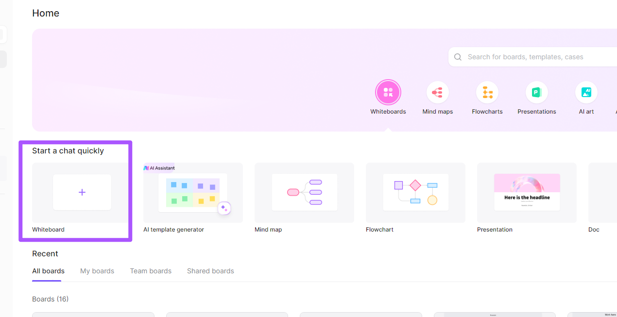
On the Boardmix Home page, click the "+" button to create a new whiteboard, then you can choose to search for available templates "topology", or directly create a new project.
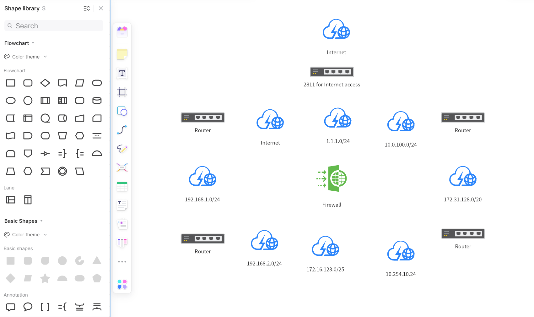
3. Select Appropriate Icons to Represent Nodes
In Boardmix, you can find various shapes and symbols to represent nodes in the network diagram. You need to find the "Shapes" and other tags in the sidebar and pick icons that suit your needs from them. Afterward, just click or drag them onto the canvas.
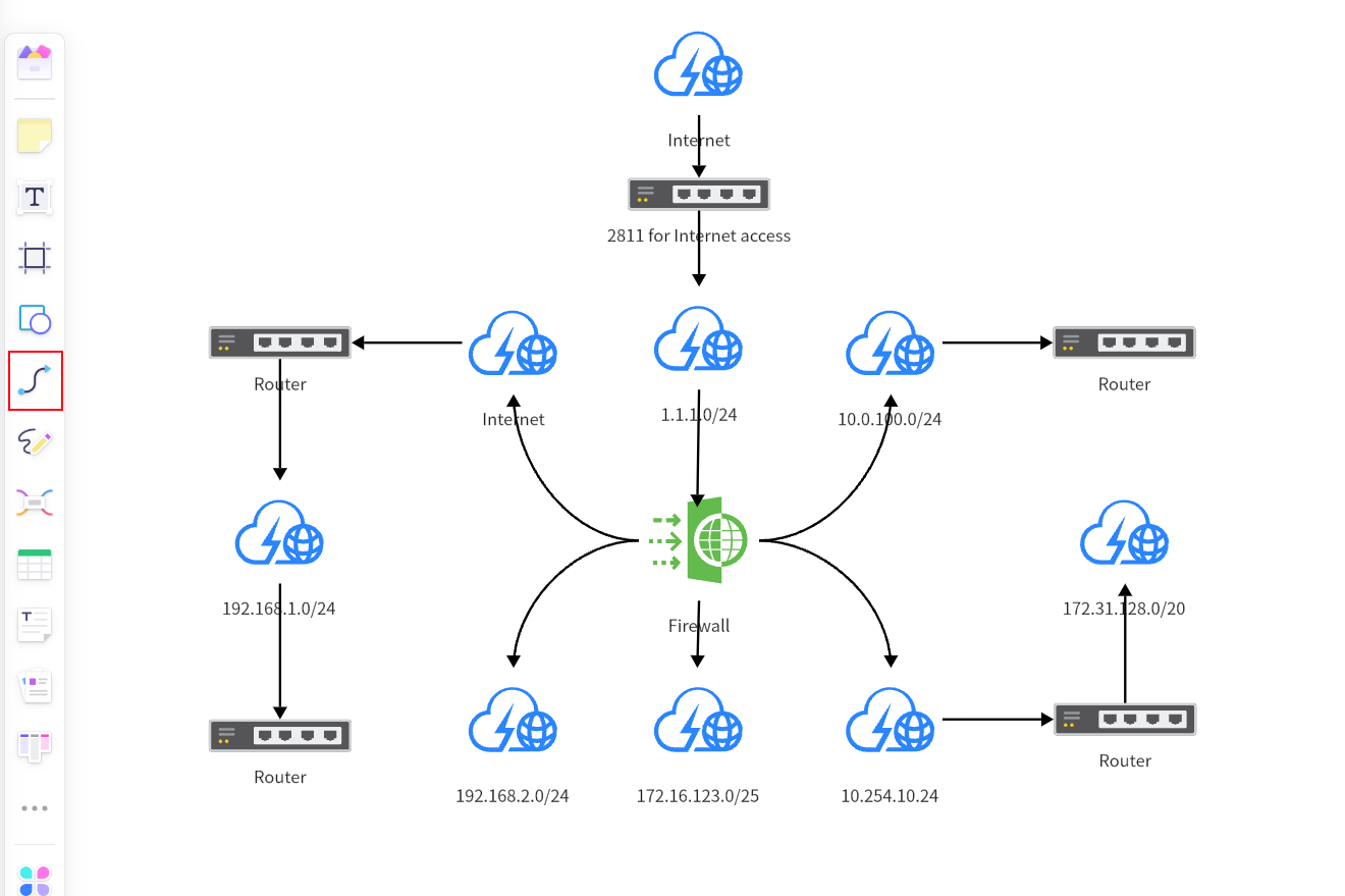
4. Connect Nodes
Once you have determined all the necessary nodes, you can start connecting them. In the toolbar, select the "Arrow" or "Connection Line" tool. Just hold down the left mouse button and drag it from one node to another node to create a connection.
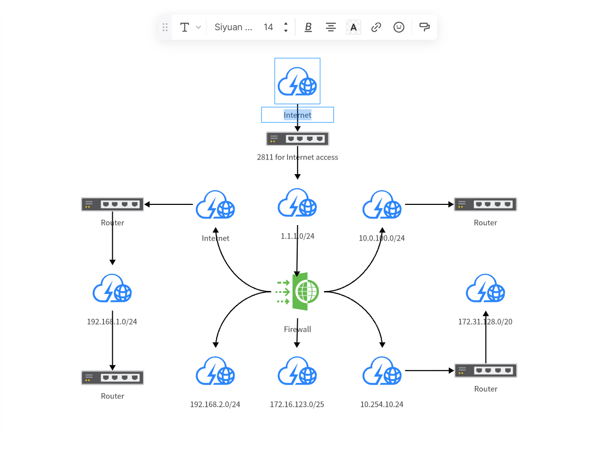
5. Label Nodes and Connections
To make your network topology diagram clearer, you can add labels to each node and connection. Select the "Text" tool, click where you need to add labels, and input relevant information.
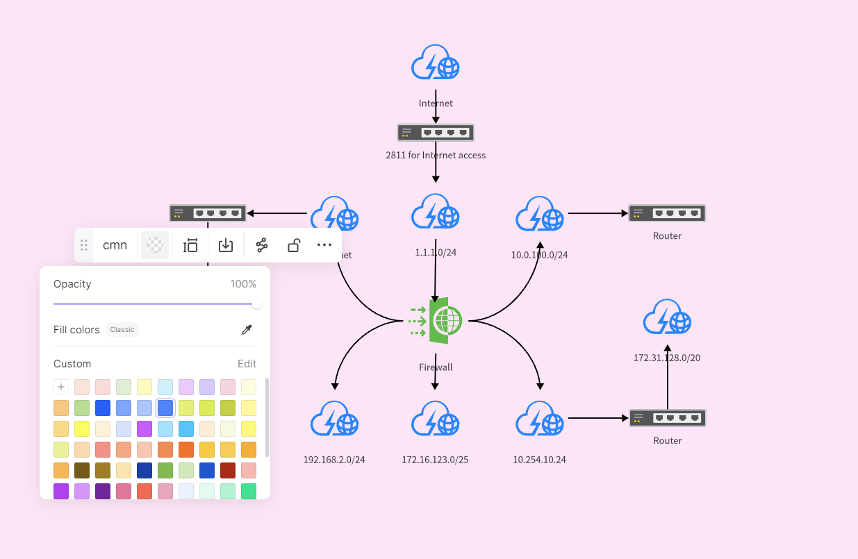
6. Refine and Adjust
After completing the above steps, you might need some fine-tuning for your network topology diagram including adjusting position sizes colors of nodes/connections, etc., making them more consistent with the actual network environment remember to save work after all edits done.
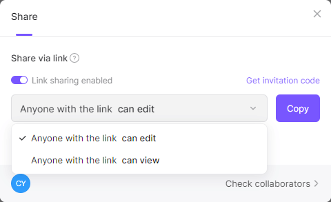
7. Share Collaborate
You can click the share button top right corner to share the project anyone collaborates to modify the topology diagram project All modifications will be synchronized on your whiteboard.
That's how to create a logical network topology diagram in Boardmix. With these steps, no matter you are an IT expert, or a student, you can easily draw clear accurate network topology diagrams.
Conclusion
In conclusion, the realm of Logical Network Topology unfolds as a critical aspect of network design and management. Understanding its essence, exploring various types, and witnessing practical applications provide valuable insights into optimizing network structures. Boardmix, as a trusted online collaborative teamwork tool, redefines the process of designing Logical Network Topology diagrams.
Boardmix emerges as an ideal platform for designing Logical Network Topology online. Its user-friendly interface and collaborative features enable teams to collaborate in real time, creating, modifying, and discussing logical network structures effortlessly. Whether it's mapping out a corporate network or optimizing a data center layout, Boardmix simplifies the design process.