Wondering how to create use case diagram? If you’re new to UML modeling, this is a common and crucial question. A use case diagram is a basic tool in system analysis and requirement modeling. It helps teams quickly sort out system functions and user needs.
This guide breaks down 6 detailed steps to help you easily learn how to make use case diagram, so you can efficiently show system functions!
What is Use Case Diagram?
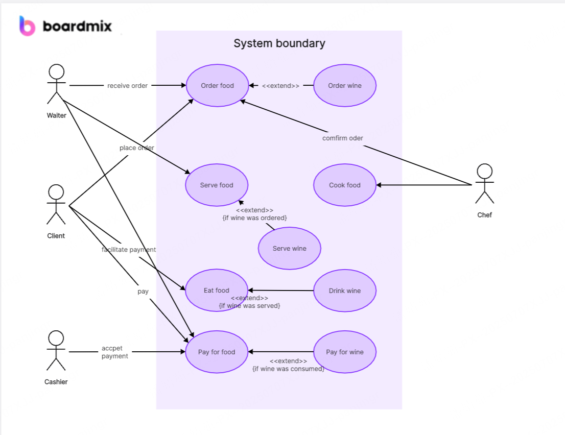
Use case diagram is a simple but powerful visual tool in UML modeling. It shows how users, called actors, interact with a system. By mapping the system’s main functions, or use cases, and linking them to the right actors, teams can see exactly what the system does. It also makes clear which business goals the system supports. Use case diagram provides a strong starting point for design and development.
The symbols are easy to understand: Stick figures represent actors, which can be people or external systems. Ovals show use cases — the specific functions or services the system provides. A rectangle marks the system boundary, which separates what is inside the system from what is outside.
What is Use of Use Case Diagram?
Use case diagram is a key tool in system analysis and planning. which simplifies how teams understand and talk about a system’s goals. And it solves common headaches including vague roles, misaligned goals, and fuzzy boundaries, making it a necessity for smooth collaboration.
✅ Clarifies Interactions
Use case diagram shows exactly how users (or actors) interact with a system. It spells out who does what, leaving no room for confusion. This clarity stops mix-ups in how different roles engage with the system.
✅ Defines Scope
Use case diagram marks the system boundary, separating what is inside the system from what is outside. This keeps teams so focused that no wasting time on irrelevant features. The project stays on track, with everyone clear on what the system should and shouldn’t do.
✅ Aligns Teams
Everyone sees the same functions and goals on the diagram. This cuts down on messy debates during requirement talks. The team moves in one direction, no detours.
✅ Spots Gaps Early
Missing functions or unclear roles jump out in the diagram. You fix these issues before design or development starts so as to save time and avoid costly rework later.
✅ Simplifies Communication
Its simple symbols—stick figures for actors, ovals for use cases—make it easy to explain system goals. Even non-technical team members get it. This broadens understanding across the whole team.
Steps to Make Use Case Diagram
Step 1: Create a New Whiteboard or Use a Template
Choosing the right use case diagram maker matters for making an efficient and clear use case diagram. Let’s use Boardmix as an example to teach you how to create use case diagram. First, sign up and log in to Boardmix, then enter the workspace.
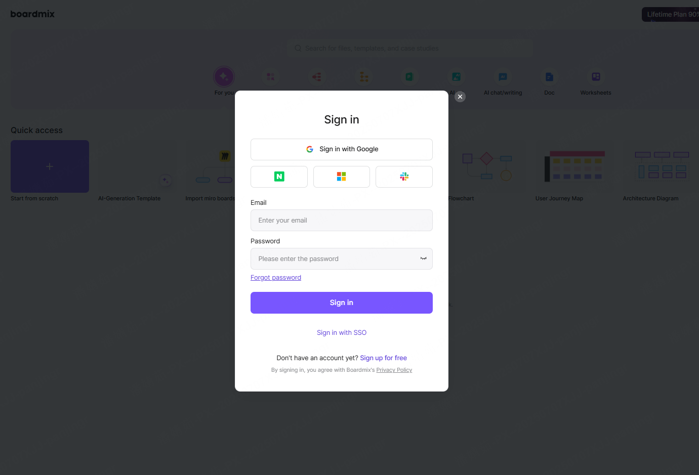
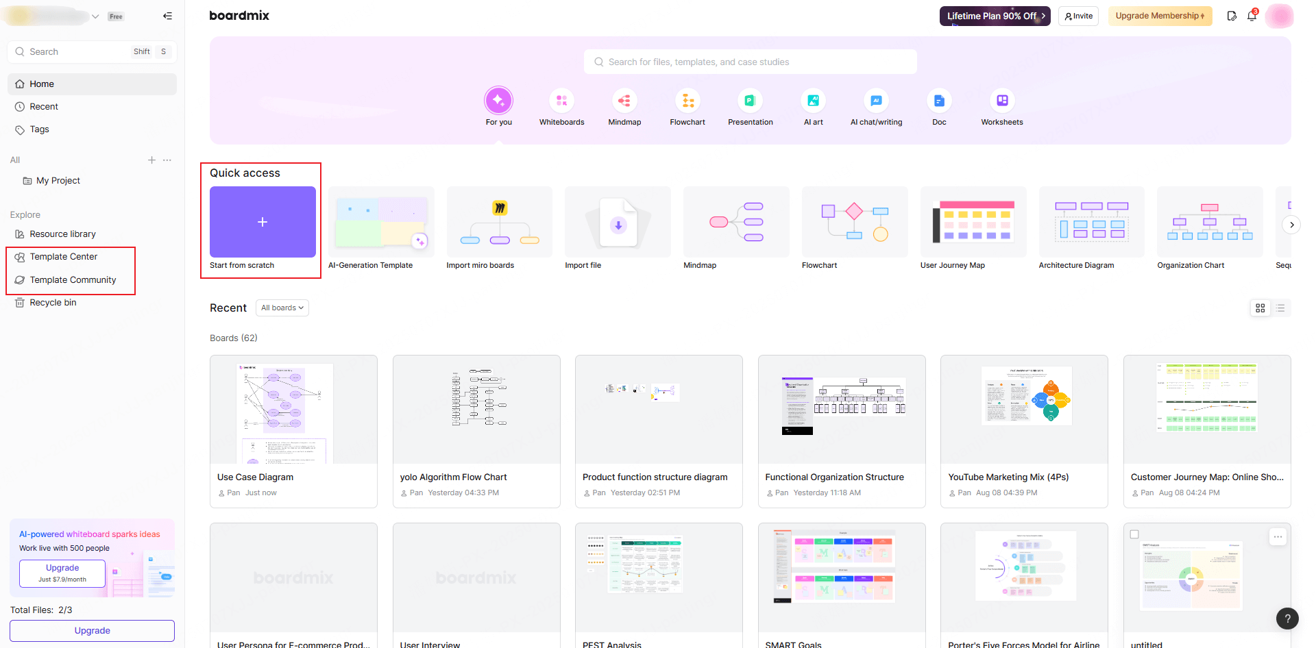
(1) Create a new whiteboard: Click "Start from scratch" to start your project.
(2) Use a use case diagram template: Click "Template Center" on the left of the workspace, search for use case diagram templates. Preview and pick the one that fits your needs.
Step 2: Define the System Boundary
(1) What is the use of defining it?
It clarifies the system’s functional scope and external interaction objects. Getting this right keeps your use case diagram focused—no irrelevant functions sneak in, ensuring it centers on core business processes.
(2) How to do it?
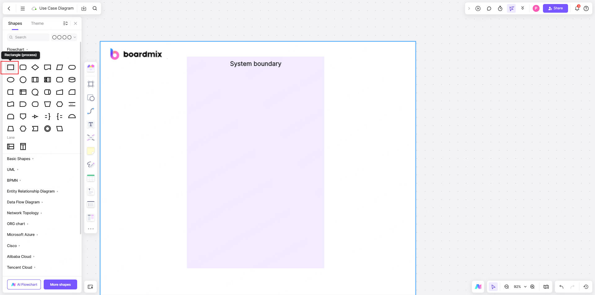
✅ Draw the system box
Select the shape library on the left or use the shortcut key R to add a rectangle. Cover the main functional area with this rectangle. Label the system name or boundary in the top center; adjust the font size for layout.
✅ Rules for boundary division
Internal functions (inside the box): Core system features like "online payment" or "order inquiry".
External elements (outside the box): External roles (users, third-party platforms) or devices that interact with the system.
Step 3: Add Actors
(1) What is the use of adding actors?
It identifies roles or external systems that interact with the system. When recognizing actors, think broadly—cover different usage scenarios and business process steps to avoid missing any. Every actor is a key node in system interaction; their behaviors and needs directly shape the creation of subsequent use cases.
(2) How to do it?
✅ Place icons: Add actors from the left shape library and position these elements outside the system box.
✅ Layout rules: Put main actors (e.g., “end users”) on the left side of the system box.
✅ Support actors (e.g., “API interface management”) go on the right.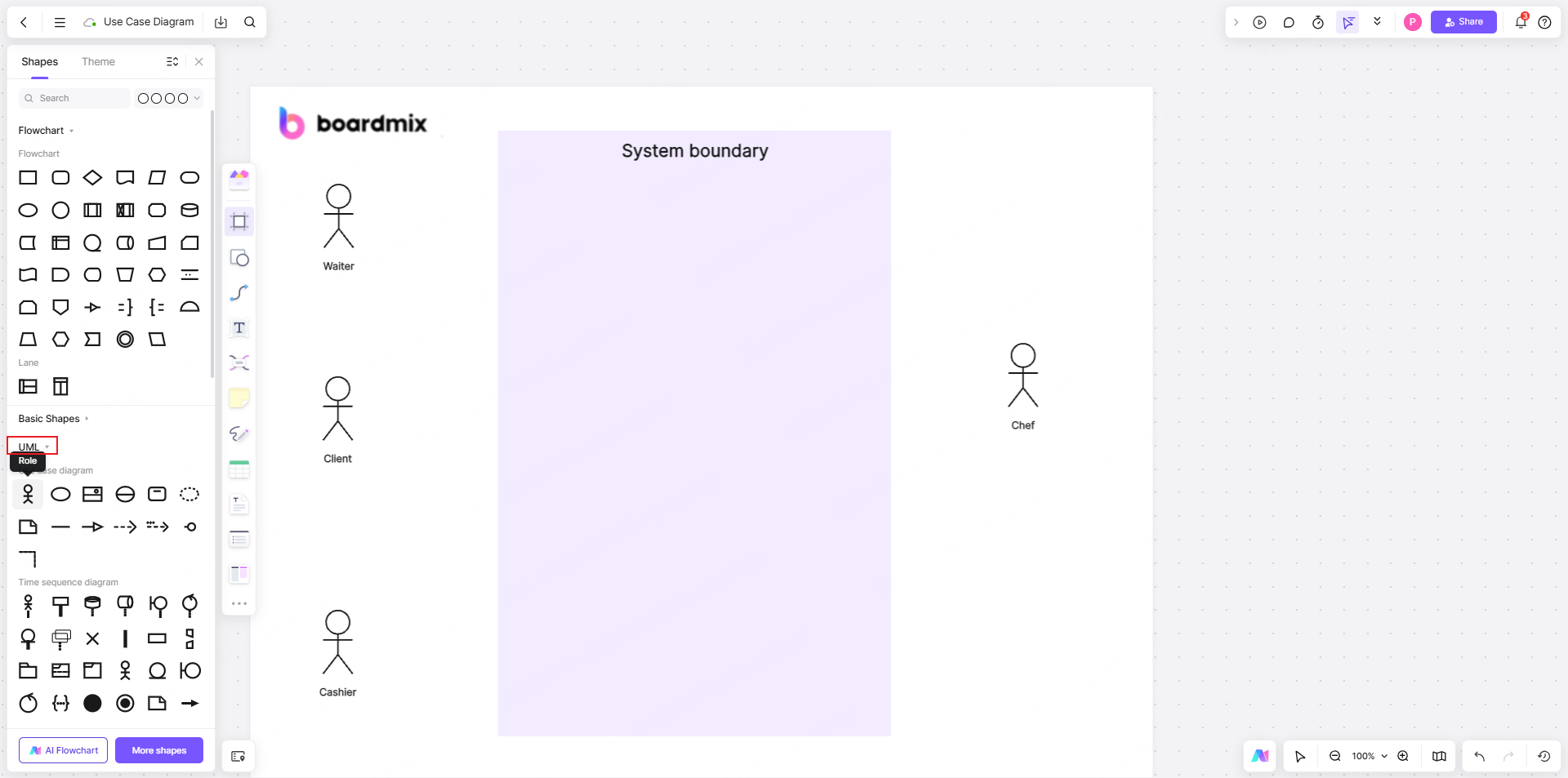
Step 4: Create Use Cases
(1) What is the use of creating use cases?
It defines specific service units provided by the system. A use case is essentially a valuable function or service scenario that the system offers to actors.
(2)How to do it?
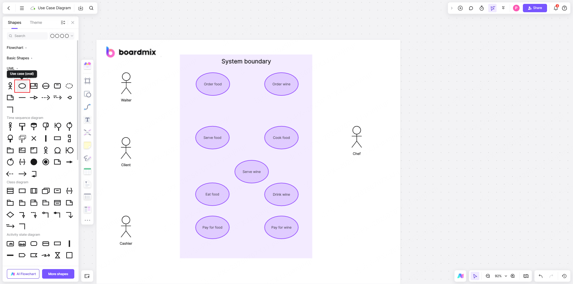
Drag and drop use cases from the left shape library to use them. Enter use case details in the shapes. When creating use cases, ensure each one fully and independently describes an interaction between an actor and the system, with clear start and end states.
Step 5: Establish Use Case Relationships
(1) What is the use of establishing use case relationships?
They describe the interaction logic between elements. Properly labeling these relationships makes the use case diagram’s logic clearer, providing more valuable references for subsequent system design, development, and testing.
(2)How to do it?
Pull lines from actor anchor points or the left-side connection tools to build use case relationships. When creating these links, start from business logic and functional connections—judge the inherent ties between use cases accurately. This clarity ensures the use case diagram better supports later system work.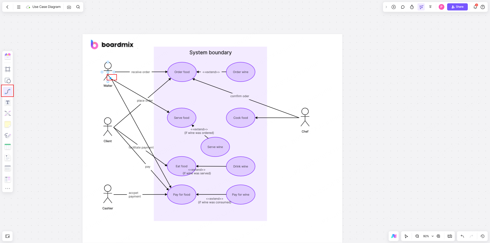
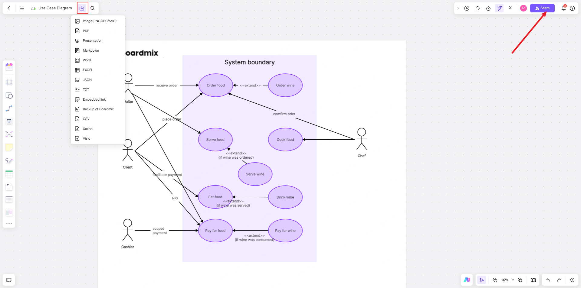
Step 6: Export and Share
Once you have finished making use case diagram, you can export it in formats like PNG or PDF—whatever fits your needs. In addition, Boardmix supports online collaboration for team: you can share the diagram’s link with your team in one click, so they can view and edit it anytime, anywhere.
Learning how to create a use case diagram isn’t tough. Follow these steps, and with boardmix, you’ll make clear, useful use case diagrams that streamline your team’s work on system analysis and requirements.
2 Examples of Use Case Diagram Applications
Example 1: Use Case Diagram for Student Information System
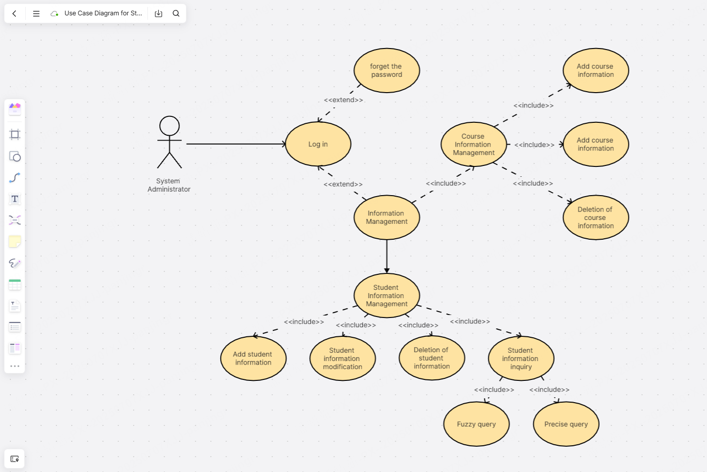
A Use Case Diagram for a Student Status Management System illustrates how various users interact with the system and what functionalities are provided to manage student information and status.
Example 2: Use Case Diagram for Hospital Appointment Registration
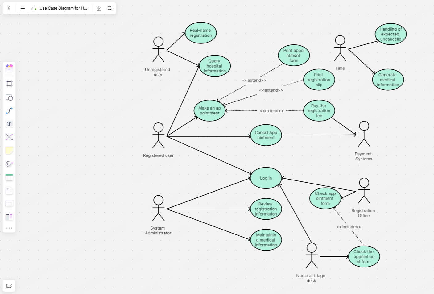
A Use Case Diagram for Hospital Appointment Registration includes key functionalities such as Patient Registration Doctor Selection, Appointment Scheduling, Confirmations. It shows interactions between patients, doctors, and the registration system, ensuring efficient appointment management.
Conclusion
A use case diagram brings different roles together under one visual, cutting down communication gaps. Its value goes beyond the diagram itself—it builds a shared language across teams.
Boardmix offers a visual collaboration space where team members can use shapes, lines, and sticky notes on a single whiteboard to express ideas creatively—boosting interaction and teamwork.
Ready to make your team’s work smoother? Try crafting a use case diagram with Boardmix. See how it turns messy requirements into clear, actionable visuals—unlocking better collaboration, faster.