Use case diagrams illustrate the relationships between actors and use cases, helping developers visualize and understand system functions. By leveraging UML use case diagrams, system users, analysts, and domain experts can discuss problems visually, reducing communication barriers and achieving consensus more easily. This article by Boardmix explains how to create UML use case diagrams.
What is a Use Case Diagram?
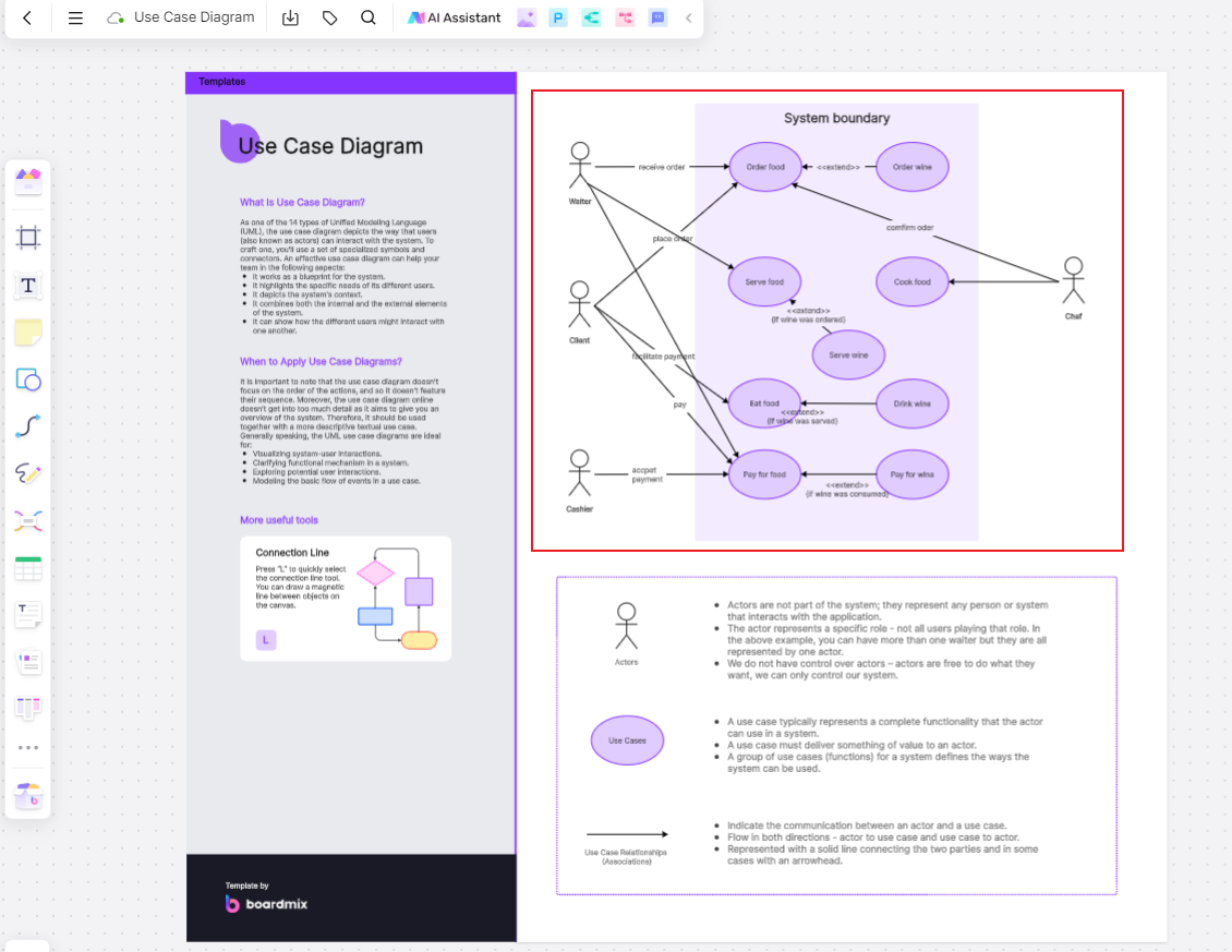
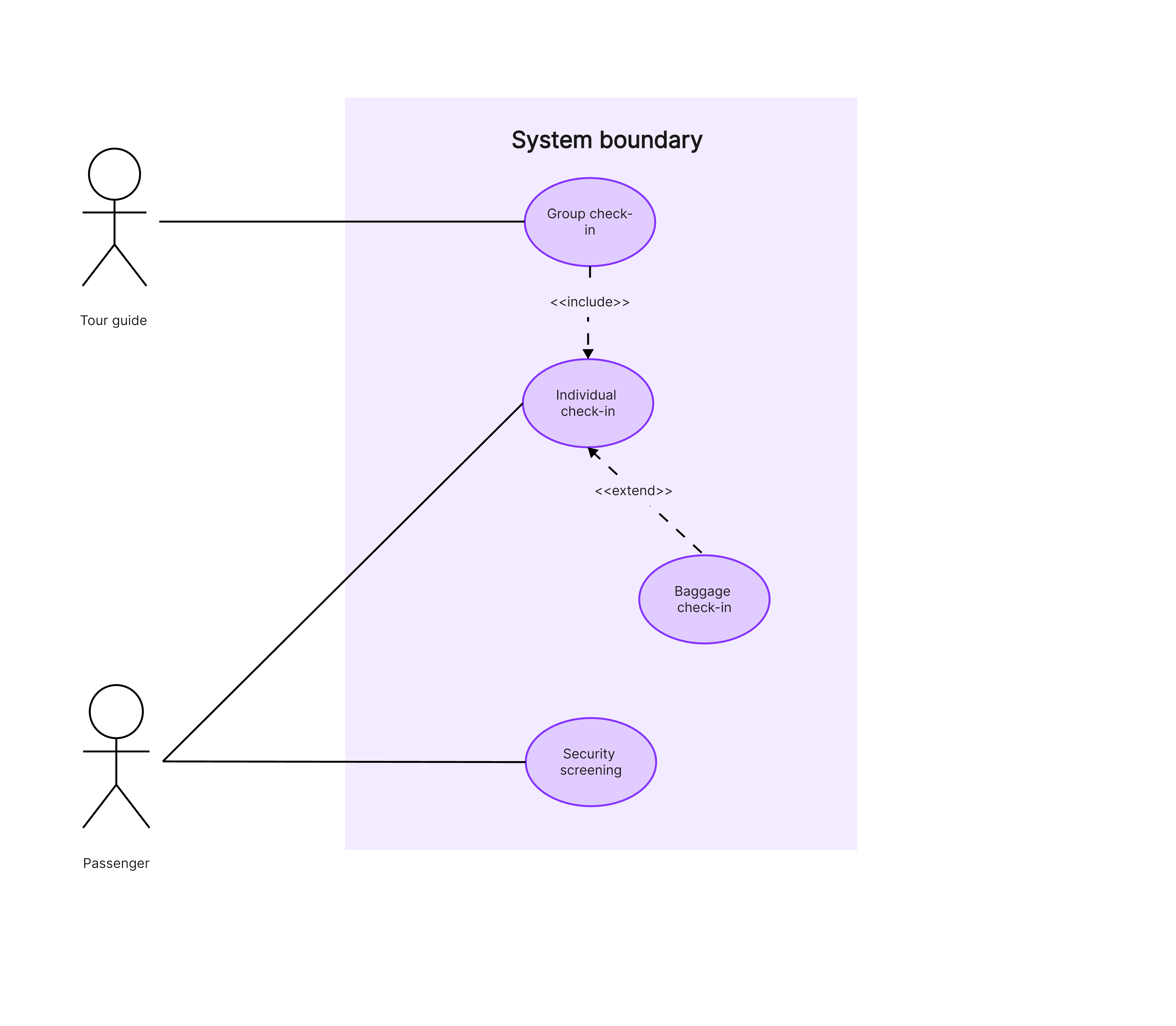
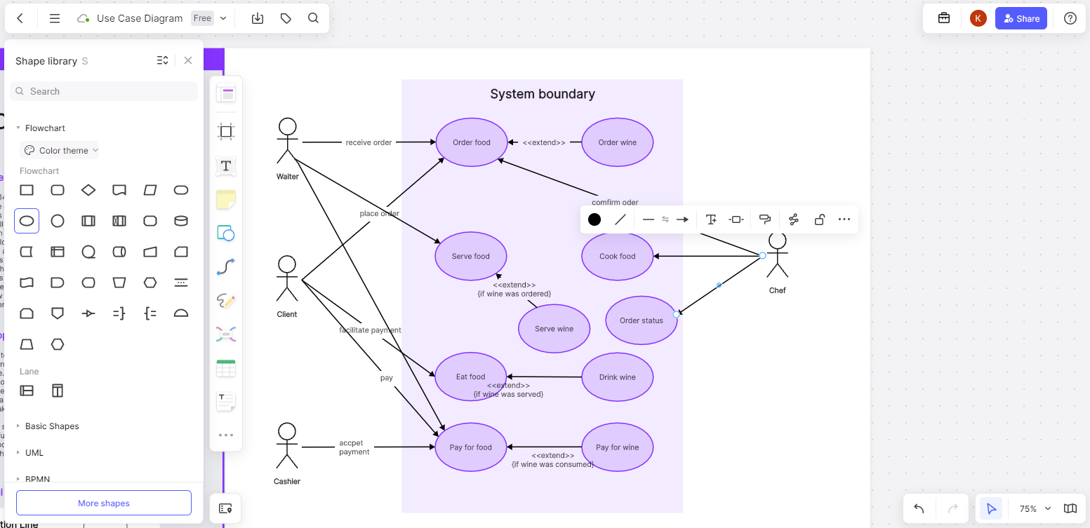
A UML use case diagram is a common tool used in requirement specifications to show the relationship between users and functional units of a system. It illustrates the system's functionality from the user's perspective and identifies the users who interact with different system functionalities. When creating a UML use case diagram, two main elements are often used: use cases and actors. Use cases are placed within the system's functional boundaries, while actors are depicted outside the system.
Uses of Use Case Diagrams
Use case diagrams reflect the system analyst's understanding of user requirements. To fully grasp user needs and ensure smooth system operation, a combination of use case diagrams and textual descriptions is essential. This combination allows clients to visualize how the system will work, understand their roles and responsibilities, and see how they will interact with the system to complete their tasks. When combined with high-fidelity prototype designs, use case diagrams provide a three-dimensional view of the requirements that need validation.
Components of a Use Case Diagram
A UML use case diagram primarily consists of three parts: actors, use cases, and the relationships between them.
Actors: Actors are not necessarily people. They represent roles that interact with the system, which could be a person, an object, another system, or even time.
Use Cases: These describe a sequence of actions, including variables, that the system performs to produce an observable result of value to a specific actor.
Relationships: The relationships between actors and use cases include associations, generalizations, inclusions, extensions, and dependencies.
-Association: This relationship indicates an interaction between an actor and a use case, represented by a solid line with an arrow pointing to the use case.
-Generalization: This shows a relationship between use cases where one use case can be a specialized form of another. It is represented by a solid line with a hollow arrow pointing to the base use case.
-Include: This indicates that the behavior of one use case (the base use case) includes the behavior of another use case. It is shown with a dashed arrow and the label <.
-Extend: This shows an optional behavior that extends the behavior of a base use case under certain conditions, represented by a dashed arrow with the label <.
Steps to Create a Use Case Diagram
Creating a UML use case diagram is straightforward. Follow these steps to draw a professional and useful UML use case diagram. We'll use the Boardmix online whiteboard software to demonstrate the steps for creating a library management system use case diagram:
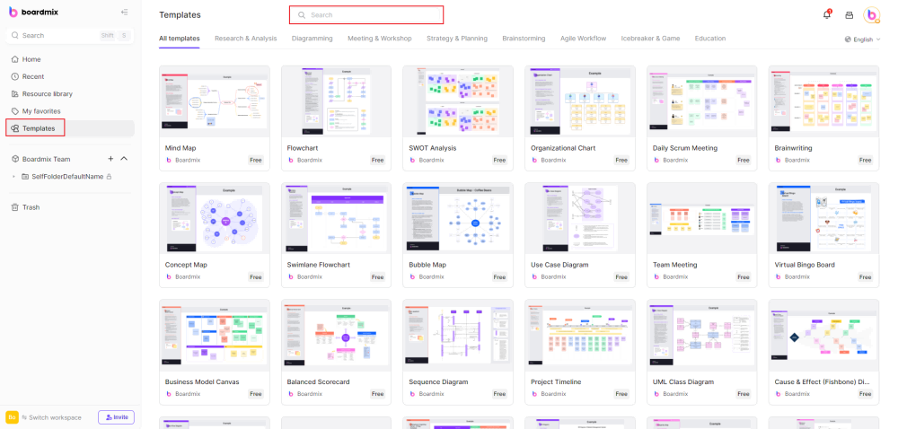
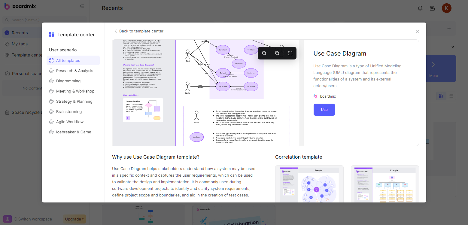
Open Boardmix: Click "Templates" or select "UML Use Case Diagram" from the template center to start drawing.
Use the Template: Click "Use" to enter the workspace. You can use existing shapes from the template or select appropriate symbols from the left toolbar. Remember, actors are represented by stick figures, use cases by oval shapes, and relationships by arrows.
Connect and Label: Connect actors and use cases according to their relationships and label the key elements. Click on arrows to edit lines, and double-click on shapes and lines to add text.
Beautify the Diagram: Use the left toolbar to enhance the diagram by adding stickers, changing fill colors, text sizes, line colors, etc.
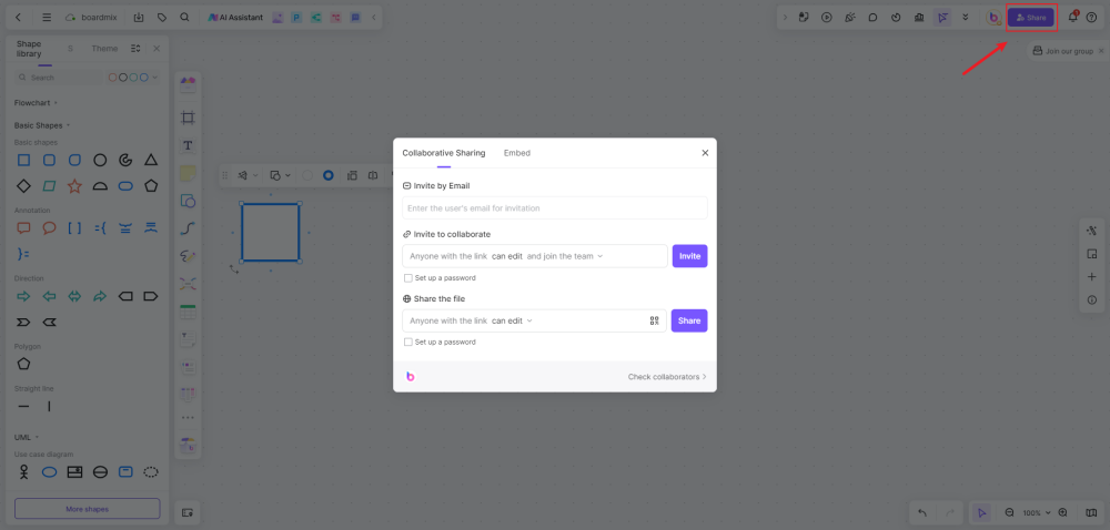
Save and Share: Boardmix saves your work in real-time. You can also export or share the diagram using the toolbar at the top to collaborate with your team.
Boardmix supports multiple devices, including computers and smartphones. Compared to other diagramming tools, Boardmix is user-friendly, with automatic alignment and snap features that make it easy to use. Even beginners can quickly create professional diagrams and effectively communicate their ideas. Just use the provided templates or arrange shapes yourself to draw a UML use case diagram.
By following these steps, you can create clear and informative UML use case diagrams that help clarify user requirements and system functionality.