Network diagrams are the foundation of all project management operations. You must understand how to construct and maintain a network diagram since it influences your project's success, failure, or repeatability.
In this article, you’ll learn all the basic knowledge of network diagrams that can be put into practice. Stay tuned.
What Is a Network Diagram in Project Management
A network diagram is a tool used by project managers to track the development and progress of activities during the life of a project. All project participants may graphically follow the course of each project phase from conception to conclusion by using project network diagrams.
In other words, they reflect the project's process. Participants in the project may have a better grasp of the activities and timeframe involved. The network diagram is a graphic with boxes and arrows. The boxes represent the tasks and responsibilities, and the arrows indicate the timeframe and order in which they must be done.
Terminologies and Types of Project Network Diagram
Terminologies
Before working with network diagrams, you need to be aware of the essential terms associated with them. These are the terms:
- Diagram template: Diagram templates contain the definition of diagram rules, layouts, and layers; that is, they hold the configuration properties which define how network diagrams will be generated (rules and layouts) and how they will be presented (diagram layers).
- Diagram Rule: A diagram rule is a specific task that executes from the initial diagram content to build the final diagram content during network diagram generation or update.
- Diagram Layout: A diagram layout is an algorithm that clarifies and normalises spacing between diagram features.
- Diagram Layer: The diagram layer is a composite layer made up of feature layers connected between the feature classes in network diagrams and the network source classes or object tables that correspond to them.
- Diagram Map: A diagram map is a canvas on which a network diagram displays by default. Any newly generated diagram opens in a diagram map view and results in creating a diagram map project item.
- Subnetwork System Diagram: A subnetwork system diagram is a network diagram representing a subnetwork. Subnetwork system diagrams are fully managed behind the scenes—created, updated, and deleted.
- Diagram Graph: The diagram graph is the mathematical structure of containers and junctions, which are connected by edges and depend on the rules specified in the related diagram template.
- Diagram Junctions: Diagram junctions are symbol point geometry and represent the network elements such as point features, junction objects, system junctions and system junction objects.
- Diagram Edges: Diagram edges are depicted as line geometry and represent the network elements such as Lines features, edge objects, junction-junction connectivity and structural attachments.
- Diagram Containers: Diagram containers represent network features or junction objects containing other network features or objects. They are usually depicted as polygon geometry.
Types of Network Diagrams
There are two kinds of network diagrams.
- Arrow Network, also known as AoA (Activity on Arrow) or ADM (Arrow Diagramming Method)
- Node Network, often known as AoN (Activity or Node) or PDM (Precedence Diagramming Method)
ADM or Arrow Network (Arrow Diagramming Method)
ADM (Arrow diagramming method) is a network diagram in which arrows are linked together by nodes to represent activities. The arrow's tail signifies the beginning of the activity, and the head of the arrow represents the end. The arrow's length is often proportional to the duration of the activity. The arrow network depicts the 'FS' (finish to start) link between activities.
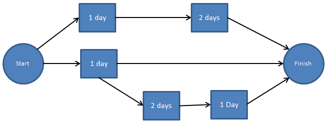
PDM or Node Network (Precedence Diagramming Method)
PDM (Precedence diagramming method) is a network diagram in which nodes or boxes are linked by arrows to represent activities. These arrows represent the connections between activities. All four linkages between activities may be illustrated using the precedence diagramming approach. These are the Finish to Start 'FS', Start to Start 'SS', Finish to Finish 'FF', and Start to Finish 'SF' connections.
How to Create a Network Diagram for Project Management
Do you wonder how to make a network diagram for project management? Then proceed with the following steps;
1. Establish the Project's Activities, Schedule, and Dependencies
The first step in developing a project network diagram is to describe all of the project activities and tasks that will be undertaken throughout the project process and the time necessary to complete them successfully.
A reasonable and transparent deadline will prevent the project team from feeling stressed. Arrange the activities so that those reliant on the completion of others are grouped and tagged together.
2. Show the Duration of All Activities in Nodes.
The following step is to insert all activities into nodes. In your network design, nodes are rectangular boxes that store project activity.
The length of each activity should be listed beneath each activity.
3. Connect Activities Using Dependencies
Define the dependencies between activities and arrange them together. An arrow connects the predecessor to the successor, with the predecessor relying on the successor, and the successor relying on the predecessor.
4. Thorough Planning of All Activities
You must make enough preparations to complete the highlighted tasks successfully. This may be accomplished by planning forward from the predecessor task to the successor task or backward.
Both techniques of planning guarantee that all relevant elements are fully addressed for the activities to achieve their predetermined deadline requirements.
5. Determine the Buffer Times
The next step is calculating each activity's cumulative buffer time (CBT) and free buffer time (BT).
6. Identify the Critical Path
The critical path of any project is the sequence of activities with the longest projected completion time from start to finish.
This is the most crucial route since even minor delays in any of the operations on this path will delay the project's anticipated completion time.
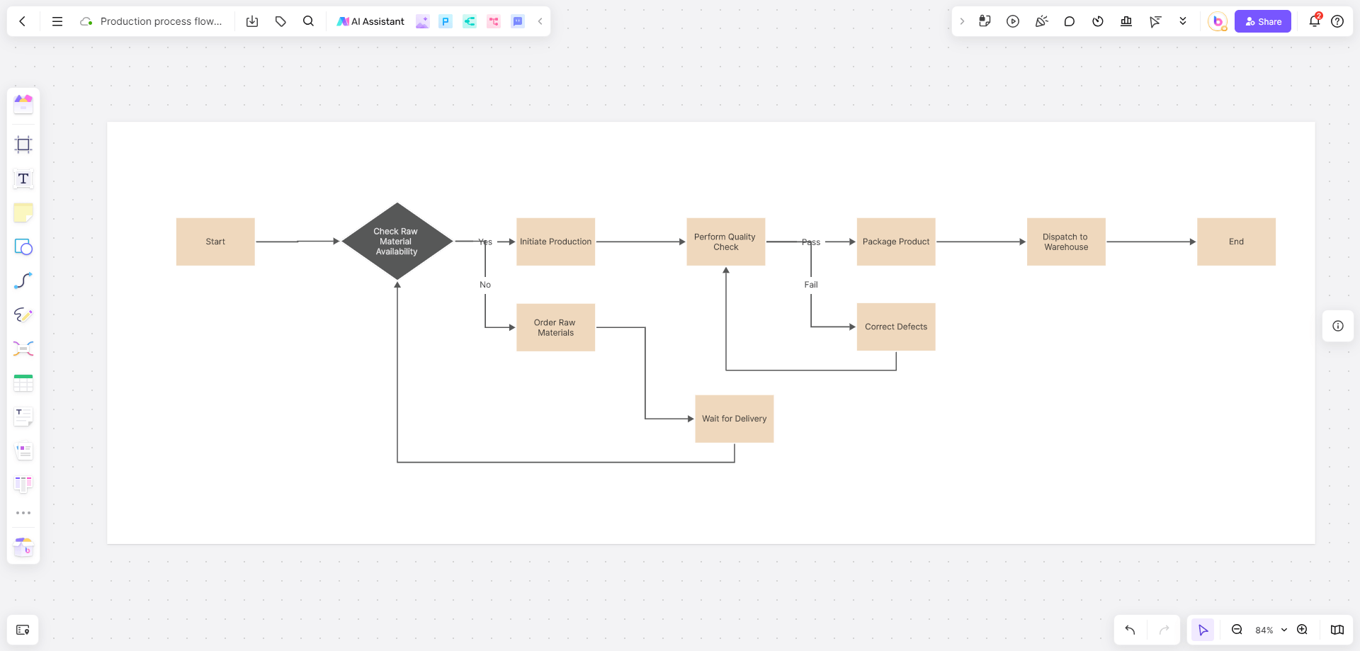
A Network Diagram Maker You Can Never Miss - Boardmix
Boardmix is a collaborative whiteboard accessible through the web and provides an all-in-one solution for collaboration, project management, and communication. It is created with various features that allow teams to collaborate and instinctively debate ideas, enhancing creativity and productivity.
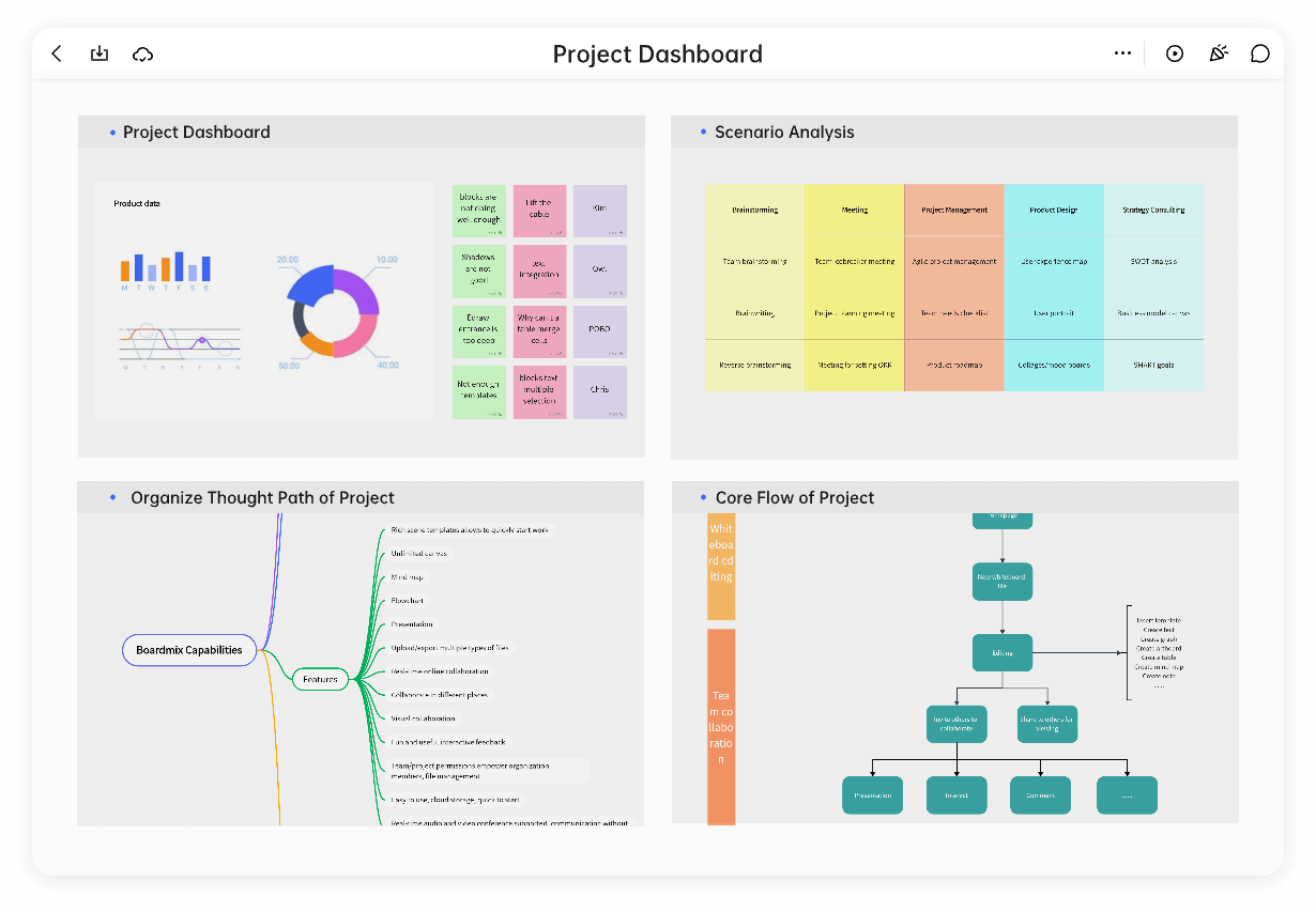
Boardmix is also the most sophisticated and user-friendly network diagram creator. Its easy-to-use interface enables teams to generate network diagrams collaboratively in real-time. It includes all fundamental tools, such as a pen, note, eraser, shape, frame, and others, for you to easily create the network design.
Furthermore, it provides various templates to help the team swiftly build diagrams in several minutes. Just give it a try right now!