



If you've ever joined a new codebase and wished someone had left behind a map, you already understand why UML exists. Unified Modeling Language (UML) diagrams give developers, architects, and product teams a shared visual language for describing how a system is structured and how its parts interact — without needing to read through thousands of lines of code first.
The challenge most teams run into isn't whether to use UML, but which diagram type fits the situation, and how to actually produce one without wrestling with clunky, outdated diagramming software. This guide walks through the core UML diagram types, when to use each one, real examples, and how to create them online without a steep learning curve.
What Is a UML Diagram, and Why Does It Matter?
UML is a standardized visual notation for modeling software systems, originally developed in the 1990s and still widely used today across engineering teams, technical documentation, and system design discussions. Rather than describing a system purely in prose or code, UML diagrams represent classes, objects, processes, and interactions visually — making complex relationships easier to understand at a glance.
UML diagrams are useful throughout the software lifecycle:
- Design and planning — mapping out a system's architecture before writing code, so the team agrees on structure early.
- Onboarding — helping new engineers understand an existing codebase faster than reading raw source files.
- Documentation — keeping a visual record of how a system works for future reference or audits.
- Communication — bridging the gap between technical and non-technical stakeholders during product discussions.
- Debugging and refactoring — visualizing dependencies and relationships to spot design issues before they become bigger problems.
UML isn't one diagram — it's a family of diagram types, each suited to a different aspect of a system. Understanding which type to reach for is often the biggest hurdle for teams new to UML.
The Two Categories of UML Diagrams
UML diagrams fall into two broad categories:
- Structural diagrams — describe the static structure of a system: its classes, objects, components, and how they relate to one another. Class diagrams and component diagrams fall here.
- Behavioral diagrams — describe how a system behaves over time: the flow of processes, interactions between objects, and how the system responds to events. Sequence diagrams, use case diagrams, and activity diagrams fall here.
Most real-world documentation uses a mix of both — structural diagrams to explain "what exists," and behavioral diagrams to explain "what happens."
Class Diagram: Mapping System Structure
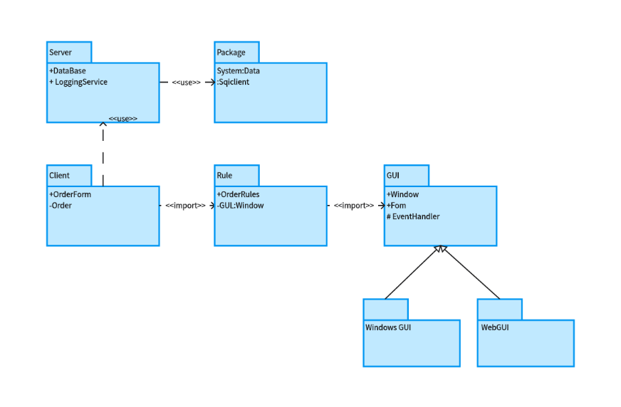
A class diagram is the most commonly used UML diagram, and often the first one teams learn. It represents the classes in a system, their attributes, methods, and the relationships between them — such as inheritance, association, and dependency.
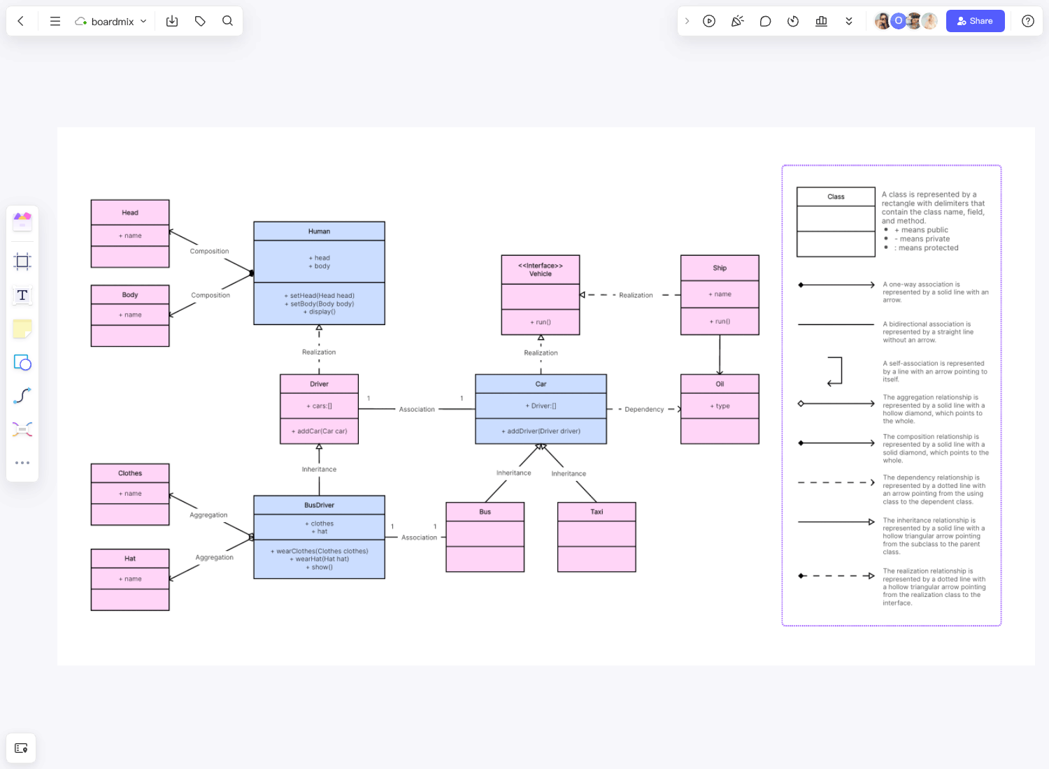
When to use it: Class diagrams are ideal during the design phase of object-oriented systems, when a team needs to agree on the data model and how different classes relate before writing code. They're also useful for documenting an existing codebase's structure for future developers.
Example: In an e-commerce system, a class diagram might show a Customer class connected to an Order class, which in turn relates to a Product class — with attributes like customerName, orderDate, and productPrice, and methods like placeOrder() or calculateTotal().
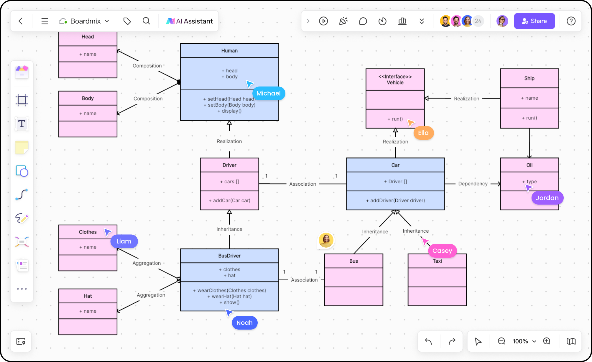
Class diagrams use specific notation for relationships — solid lines for association, hollow triangles for inheritance, diamonds for aggregation and composition — which is part of why a dedicated diagramming tool with proper UML shape libraries matters more here than in simpler flowcharts.
Sequence Diagram: Visualizing Interactions Over Time
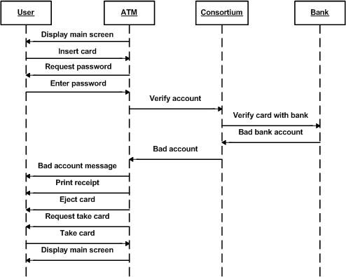
A sequence diagram shows how objects interact with one another in a particular sequence of events, typically over the lifespan of a single process or use case. It reads left to right, with each participant represented as a vertical lifeline, and messages between them shown as horizontal arrows in chronological order.
When to use it: Sequence diagrams are especially useful for documenting API calls, authentication flows, or any process where the order of operations matters — such as a user logging in, a payment being processed, or a request moving through microservices.
Example: A login sequence diagram might show a User sending credentials to a Frontend, which calls an Auth Service, which queries a Database, and returns a token back up the chain — with each step represented as a labeled arrow between lifelines.
Sequence diagrams are particularly helpful for debugging distributed systems, where understanding the exact order of calls between services can be the difference between finding a bug quickly and spending hours tracing logs.
Use Case Diagram: Capturing System Functionality from a User's Perspective
A use case diagram shows the functional requirements of a system from the perspective of its users (called "actors"). It focuses less on internal logic and more on what the system does for whom — making it a useful bridge between product requirements and technical design.
When to use it: Use case diagrams are valuable early in a project, during requirements gathering, when the team needs to align on what a system should do before diving into implementation details. They're also useful in stakeholder discussions since they're easier for non-engineers to read than class or sequence diagrams.
Example: For a ride-sharing app, a use case diagram might show a Rider actor connected to use cases like "Book a Ride," "Track Driver," and "Rate Trip," while a Driver actor connects to "Accept Ride" and "Navigate to Pickup."
Other Common UML Diagram Types
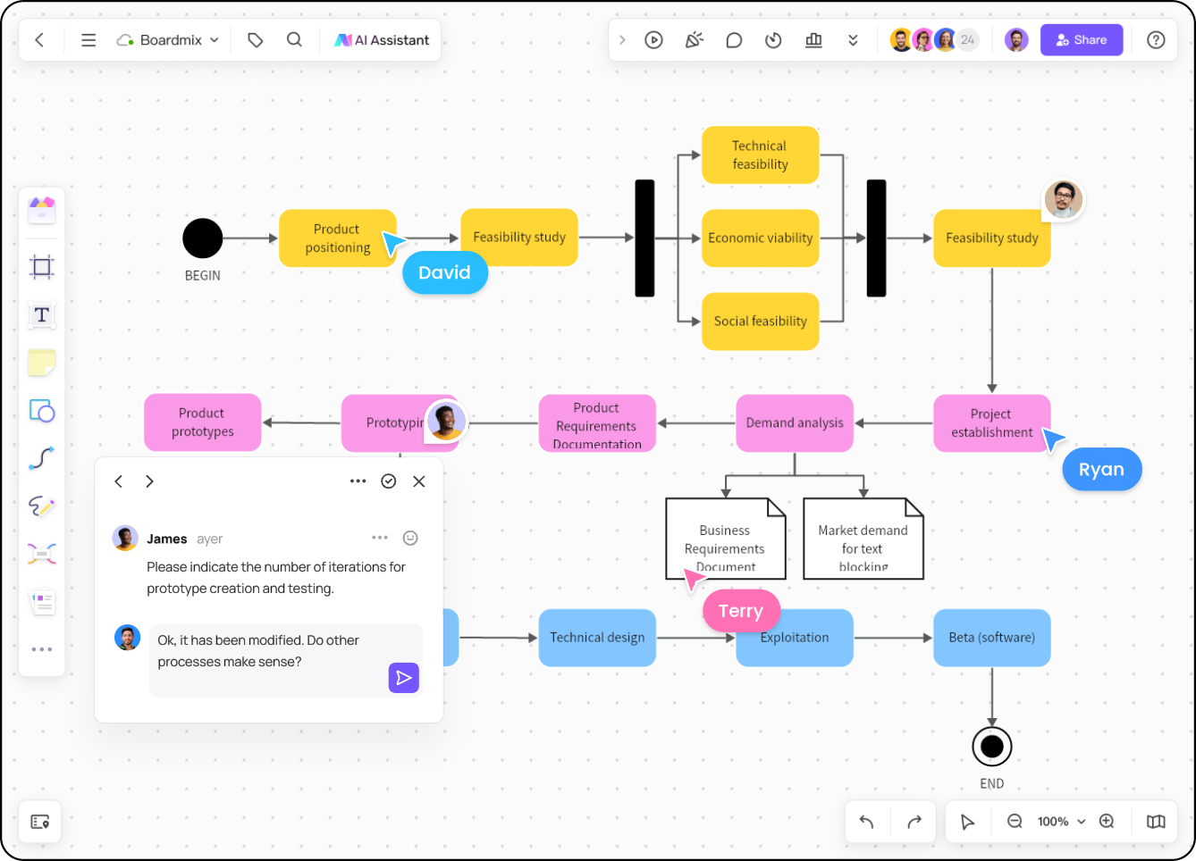
Beyond the three most widely used types above, several other UML diagrams serve more specialized purposes:
- Activity diagram — models workflows and business processes as a flowchart-like sequence of actions, useful for mapping decision logic or multi-step processes.
- State diagram — shows the different states an object can be in and the transitions between them, commonly used for modeling things like order statuses or connection states.
- Component diagram — represents how a system is divided into components and the interfaces between them, useful for high-level architecture discussions.
- Deployment diagram — models the physical architecture of a system, showing how software components are distributed across hardware or infrastructure (servers, devices, cloud instances).
- Object diagram — a snapshot of instances of classes at a specific point in time, useful for illustrating a class diagram with real example data.
Most teams don't need all of these regularly — class, sequence, and use case diagrams cover the majority of day-to-day documentation needs, with activity and component diagrams coming up for process mapping and architecture discussions respectively.
How to Choose the Right UML Diagram Type
A simple way to decide which diagram to use is to ask what question you're trying to answer:
- "What does the system look like structurally?" → Class diagram or component diagram.
- "What happens, step by step, during this process?" → Sequence diagram or activity diagram.
- "What can users actually do with this system?" → Use case diagram.
- "What states can this object be in?" → State diagram.
- "How is this system physically deployed?" → Deployment diagram.
In practice, many technical documents combine two or three diagram types — for example, a use case diagram to establish scope, followed by sequence diagrams for the key workflows, and a class diagram to define the underlying data model.
Creating UML Diagrams Online with Boardmix
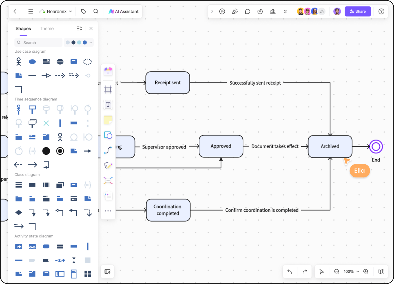
Traditional UML tools have a reputation for being either overly rigid (forcing strict notation with little flexibility) or clunky to collaborate in, especially when a team needs to review or edit a diagram together. Boardmix approaches UML diagramming as part of a broader collaborative canvas, which makes it a practical option for teams that want both proper UML notation and easy real-time collaboration.
Here's how Boardmix supports UML diagramming specifically:
- Dedicated UML shape libraries: Boardmix includes pre-built shapes and connectors for class diagrams, sequence diagrams, use case diagrams, and more, so teams don't need to manually draw standard UML notation like inheritance arrows or actor icons.
- Templates to start from: Rather than building a diagram from a blank canvas, Boardmix offers UML templates that teams can adapt to their specific system, saving setup time.
- Real-time collaboration: Multiple team members can work on the same UML diagram simultaneously — useful during architecture reviews or design discussions where several engineers need to weigh in.
- AI-assisted diagram generation: Boardmix's AI tools can help generate a starting diagram structure from a text description, which is particularly useful when sketching out a rough system design before refining the details manually.
- Flexible canvas: Because Boardmix diagrams live on an infinite canvas, teams can place a class diagram next to related sequence diagrams or notes, keeping related documentation visually connected rather than scattered across separate files.
- Easy sharing and export: Diagrams can be shared via link for stakeholder review or exported for inclusion in technical documentation.
Boardmix is the most noticeable for teams that want UML diagramming integrated into a broader collaborative whiteboard — where a class diagram, a related brainstorm, and a project roadmap can all live on connected boards rather than in separate, siloed files.
A Simple Workflow for Creating a UML Diagram Online
Regardless of which diagram type you're building, the general process looks similar:
- Identify the goal. Decide what question the diagram needs to answer — structure, interaction, or functionality — and choose the appropriate UML type accordingly.
- Start from a template. Using a pre-built UML template saves time on layout and notation, letting you focus on the actual system logic.
- Add the core elements. Place classes, actors, or lifelines first, then connect them with the appropriate relationship lines (association, inheritance, message arrows, etc.).
- Label clearly. Add attribute names, method signatures, or message descriptions so the diagram is understandable without additional explanation.
- Review with the team. Share the diagram for feedback — this is where real-time collaboration tools save significant back-and-forth compared to emailing static image files.
- Keep it updated. UML diagrams lose value quickly if they fall out of sync with the actual system. Treat them as living documentation, not a one-time deliverable.
Common Mistakes to Avoid
- Overcomplicating the diagram. Trying to capture every detail of a system in a single diagram often makes it harder to read, not easier. Split complex systems into multiple, focused diagrams.
- Mixing diagram types. Combining class diagram notation with sequence diagram elements in the same view creates confusion. Keep each diagram type consistent with its standard notation.
- Letting diagrams go stale. A UML diagram that doesn't reflect the current system can be more misleading than having no diagram at all.
- Skipping the "why." A diagram without context can be hard for newcomers to interpret. A short description or title explaining the diagram's purpose goes a long way.
Frequently Asked Questions
Which UML diagram is most commonly used?
Class diagrams and sequence diagrams tend to be the most frequently used in day-to-day software development, since they cover system structure and process flow — the two things engineering teams most often need to communicate.
Can I create UML diagrams without installing software?
Yes. Online tools like Boardmix allow you to create UML diagrams directly in the browser, with no installation required, and support real-time collaboration for team review.
Is UML still relevant in 2026?
Yes, particularly for documenting system architecture, onboarding new engineers, and communicating technical designs to cross-functional teams. While not every team uses formal UML notation for every project, the core diagram types remain a common reference point in software design discussions.
What's the difference between a use case diagram and a sequence diagram?
A use case diagram shows what a system does from a user's perspective at a high level, without detailing the internal steps. A sequence diagram shows the detailed, step-by-step interaction between components or objects for a specific process.
Do I need to follow strict UML notation rules?
It depends on your context. Formal environments (academic settings, regulated industries, or strict documentation standards) may require close adherence to UML specification. Many product and engineering teams use a more relaxed version of UML notation, prioritizing clarity for their team over strict formal compliance.
Final Thoughts
UML diagrams remain one of the most effective ways to communicate how a system is built and how it behaves — as long as you choose the right diagram type for the question you're trying to answer. Class diagrams for structure, sequence diagrams for interaction, use case diagrams for functionality, and the other UML types for their specific niches.
The tooling you use matters too. A diagramming tool that supports proper UML notation, offers templates to speed up setup, and makes it easy for a team to review and edit together will save significant time compared to static, single-user diagramming software.
Try Boardmix's UML templates and shape libraries to sketch out your next class diagram, sequence diagram, or system architecture — directly in the browser, with your team.